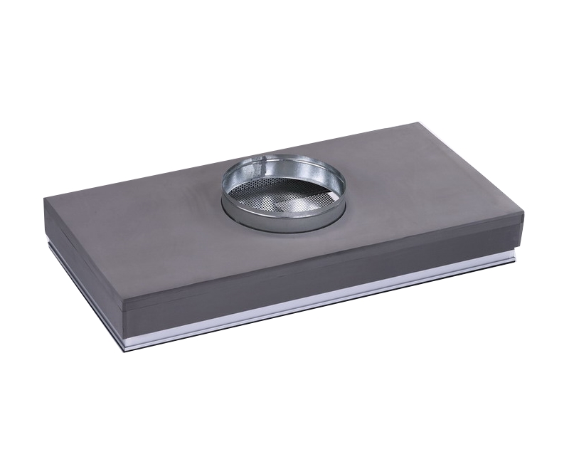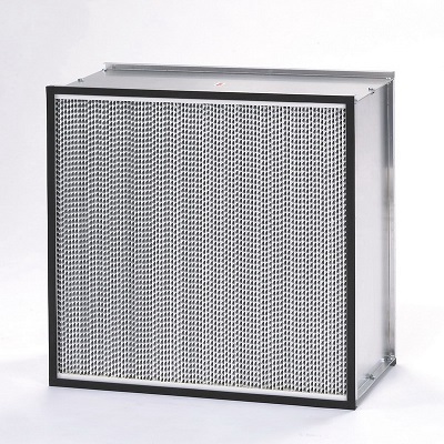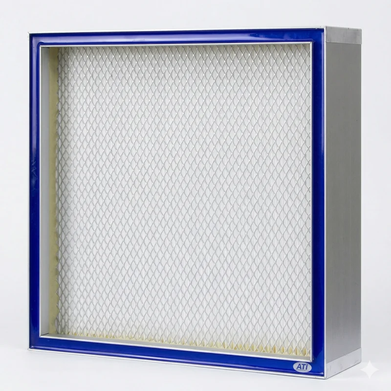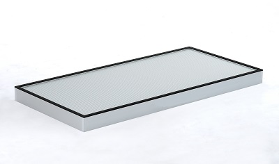
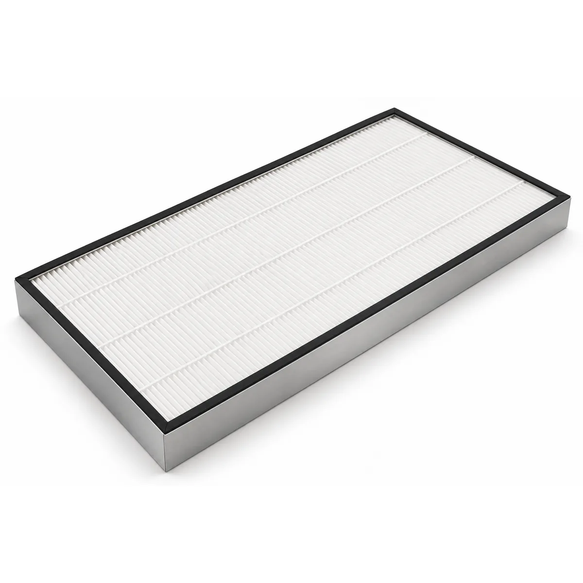
PTFE Membrane HEPA / ULPA Filter (Boron-Free, Low Pressure Drop)
Product Overview
Key Specifications
- Efficiency Class
- H13 / H14 / U15 / U16 / U17
- Filtration Efficiency
- H13 ≥ 99.95% to U17 ≥ 99.999995% (MPPS)
- Initial Pressure Drop
- 44–102 Pa @0.45 m/s
- Depth
- 50 / 52 / 69 / 70 / 86 / 88 / 90 mm



Specifications
- Filter Media
- ePTFE microporous membrane laminated to non-woven support (boron-free, binder-free)
- Frame
- Anodized aluminum frame
- Structure
- Mini-pleat
- Separator
- Hot-melt bead separators
- Gasket
- Gaskets on both faces (gasket frame); knife-edge frame for gel channel
- Test Standard
- EN 1822 / ISO 29463
- Efficiency Class
- H13 / H14 / U15 / U16 / U17
- Filtration Efficiency
- H13 ≥ 99.95% to U17 ≥ 99.999995% (MPPS)
- Rated Airflow
- 526–2,218 m³/h @0.45 m/s
- Face Velocity
- 0.45 m/s
- Initial Pressure Drop
- 44–102 Pa @0.45 m/s
- Final Pressure Drop
- Replace at twice the initial pressure drop
- Standard Dimensions
- 570×570, 610×610, 570×1170, 610×760, 610×1220, 1170×1170 mm
- Depth
- 50 / 52 / 69 / 70 / 86 / 88 / 90 mm
- Custom Sizes
- Sizes, depths and frame types made to drawing
- Max. Operating Temperature
- ≤ 70°C
- Max. Relative Humidity
- 100% RH (non-condensing)
- Applications
- Semiconductor and display cleanroom FFUs, pharmaceutical aseptic areas, hospital operating rooms, tool mini-environments, exhaust containing acid / alkaline gases
- Leak Test
- Every filter scan-tested before shipment with report; low-concentration PAO or PSL recommended in the field
- Certification
- UL 900 (optional)
Some values are typical ranges for this product class; the shipped datasheet governs.
Standard models and specifications
| Model | Grade | Efficiency (MPPS) | Size W×H×D (mm) | Rated airflow (m³/h) | Face velocity (m/s) | Initial ΔP (Pa) | Frame |
|---|---|---|---|---|---|---|---|
| PTFE-MH95-610-610-69 * | H13 | ≥ 99.95% | 610 × 610 × 69 | 603 | 0.45 | 44 | Gasket frame |
| PTFE-MH95-570-1170-69 * | H13 | ≥ 99.95% | 570 × 1170 × 69 | 1,080 | 0.45 | 44 | Gasket frame |
| PTFE-MH995-610-610-69 * | H14 | ≥ 99.995% | 610 × 610 × 69 | 603 | 0.45 | 58 | Gasket frame |
| PTFE-MH995-570-1170-69 * | H14 | ≥ 99.995% | 570 × 1170 × 69 | 1,080 | 0.45 | 58 | Gasket frame |
| PTFE-MH995-610-1220-69 * | H14 | ≥ 99.995% | 610 × 1220 × 69 | 1,206 | 0.45 | 58 | Gasket frame |
| PTFE-MH995-1170-1170-69 * | H14 | ≥ 99.995% | 1170 × 1170 × 69 | 2,218 | 0.45 | 58 | Gasket frame |
| PTFE-MU9995-570-570-50 | U15 | ≥ 99.9995% | 570 × 570 × 50 | 526 | 0.45 | < 73 | Gasket frame |
| PTFE-MU9995-570-1170-50 | U15 | ≥ 99.9995% | 570 × 1170 × 50 | 1,080 | 0.45 | < 73 | Gasket frame |
| PTFE-MU9995-570-1170-70 | U15 | ≥ 99.9995% | 570 × 1170 × 70 | 1,080 | 0.45 | < 73 | Knife-edge (gel) |
| PTFE-MU9995-570-1170-88 | U15 | ≥ 99.9995% | 570 × 1170 × 88 | 1,080 | 0.45 | < 73 | Knife-edge (gel) |
| MU9999-610-760-86 | U15 | ≥ 99.9999% | 610 × 760 × 86 | 1,140 | 0.68 | 142 | Gasket frame |
| MU99995-570-1170-52-PTFE | U16 | ≥ 99.99995% | 570 × 1170 × 52 | 1,110 | 0.46 | 102 | Gasket frame |
| PTFE-MU99995-1170-1170-90 * | U16 | ≥ 99.99995% | 1170 × 1170 × 90 | 2,218 | 0.45 | 83 | Knife-edge (gel) |
| PTFE-MU999995-570-1170-90 * | U17 | ≥ 99.999995% | 570 × 1170 × 90 | 1,080 | 0.45 | 97 | Knife-edge (gel) |
| PTFE-MU999995-1170-1170-90 * | U17 | ≥ 99.999995% | 1170 × 1170 × 90 | 2,218 | 0.45 | 97 | Knife-edge (gel) |
Model codes are our ERP item codes. Airflow is calculated from nominal size; pressure drop is the initial value for a new filter. * Models are standard specifications numbered by the same rule; their pressure drops are typical values and the order specification sheet governs.
Detailed Description
What is a PTFE HEPA / ULPA filter
A PTFE (polytetrafluoroethylene, often called Teflon) HEPA / ULPA filter uses PTFE stretched into a microporous membrane (ePTFE), laminated to a non-woven support layer, mini-pleated and mounted in an aluminum frame. Compared with a conventional glass-fiber filter it differs in three key ways: about one-third to one-half lower pressure drop at the same grade, no boron or phosphorus, so no dopants are released into the process, and resistance to acids, alkalis and moisture. These are exactly the concerns of semiconductor, display and pharmaceutical cleanrooms, which is why more and more FFUs and ceiling ULPA filters in advanced fabs specify PTFE media. This page covers five EN 1822 grades from H13 to U17 in common cleanroom sizes such as 570×1170, 610×610 and 1170×1170 mm. Every filter is scan-tested for leaks before shipment and supplied with a test report, and UL 900 fire rating is available as an option.Surface filtration vs depth filtration
Surface filtration vs depth filtration
Media cross-section: glass-fiber paper on the left, PTFE membrane laminate on the right
Schematic; thickness and particle size are exaggerated.
About one-third to one-half lower pressure drop at the same grade
Initial pressure drop by grade: PTFE vs glass fiber
Dots are models on this page (0.45 m/s); grey bands are the estimated range for glass fiber of the same grade
PTFE values are from the model table; U15 is an upper limit. The glass-fiber range is estimated from the pressure-drop ratio in patent and academic sources (PTFE about 1/2 to 2/3 of glass fiber) and is for comparison only.
Why semiconductor and display fabs specify boron-free PTFE
Glass fiber in conventional HEPA / ULPA filters is borosilicate glass. Hydrofluoric acid (HF) vapor drifting from etch and wet-clean areas attacks the glass and produces boron-containing gases such as boron trifluoride (BF₃), which are carried into the cleanroom. Boron is a p-type dopant for silicon, and when it deposits on the wafer surface it shifts device electrical characteristics. The binder in glass-fiber media can also release organics and become one source of AMC (airborne molecular contamination). A PTFE membrane contains no boron, phosphorus or metals, needs no binder and resists HF, eliminating both sources of contamination. The more advanced the process, the more sensitive it is to AMC: EUV lithography, gate oxidation and thin-film deposition areas typically require U16–U17 efficiency and boron-free media together, with chemical filters upstream to handle acid, alkaline and organic gases.PTFE vs glass-fiber filters
| Property | PTFE membrane media | Glass-fiber media |
|---|---|---|
| Capture mechanism | Surface filtration: the microporous membrane stops particles at the surface | Depth filtration: particles captured layer by layer in the fiber mat |
| Initial pressure drop at same grade | About 1/2 to 2/3 of glass fiber | Baseline |
| Boron, phosphorus, metals | None, nothing released | Borosilicate fiber and binder may release them |
| Organic outgassing | Very low (no binder) | Binder may release organics |
| Acid, alkali and HF resistance | Excellent, PTFE is chemically inert | HF attacks the glass and forms BF₃ |
| Moisture resistance | Hydrophobic, humidity does not affect efficiency | Strength and efficiency may drop when wet |
| Folding and fiber shedding | Tough membrane, does not crack or shed | Brittle fibers, prone to tears in pleating and handling |
| Dust-holding capacity | Low, needs pre-filter protection | Higher |
| PAO oil-aerosol leak test | High concentrations clog the membrane; use low concentration or PSL | Tolerates normal PAO scanning |
| Unit price | Higher | Lower |
Choosing an EN 1822 grade
| Grade | Integral efficiency (MPPS) | Local efficiency (MPPS) | Penetration | Typical use |
|---|---|---|---|---|
| H13 | ≥ 99.95% | ≥ 99.75% | 0.05% | Hospitals, biotech labs, equipment exhaust |
| H14 | ≥ 99.995% | ≥ 99.975% | 0.005% | Pharmaceutical aseptic areas, ISO 5 cleanrooms |
| U15 | ≥ 99.9995% | ≥ 99.9975% | 0.0005% | Semiconductor back-end, display fab FFUs |
| U16 | ≥ 99.99995% | ≥ 99.99975% | 0.00005% | Semiconductor front-end ISO 3–4 areas |
| U17 | ≥ 99.999995% | ≥ 99.9999% | 0.000005% | Advanced-node ISO 1–3, tool mini-environments |
Types and selection guide
| Application | Recommended grade | Recommended type | Pre-filtration |
|---|---|---|---|
| Semiconductor front-end: lithography, etch, thin film | U16–U17 | Knife-edge frame + gel channel (PTFE-MU999995 series) | Chemical filter + F9 medium filter |
| Semiconductor back-end, display, PCB | U15 | 570×1170 for FFUs (PTFE-MU9995 series) | F8–F9 medium filter |
| Pharmaceutical aseptic filling, isolators | H14 | Gasket frame (PTFE-MH995 series) | F9 medium filter |
| Hospital operating rooms, biotech labs | H13–H14 | Gasket frame (PTFE-MH95 / MH995 series) | F7–F9 medium filter |
| Humid exhaust or exhaust with acid / alkaline gases | H13–H14 | Gasket frame | Pre-filter + medium filter |
PTFE media sheets
| Media code | Efficiency (0.3 µm) | Basis weight (g/m²) | Thickness (mm) | Pressure drop @5.3 cm/s | Sheet size |
|---|---|---|---|---|---|
| PTFE99-1.2-1.2 | ≥ 99.99% | 90 (70–110) | 0.45 (0.25–0.65) | 145 Pa (130–160) | 1.2 × 1.2 m |
| PTFE999-1.2-1.2 * | ≥ 99.999% | 90 (70–110) | 0.45 (0.25–0.65) | 200 Pa (180–220) | 1.2 × 1.2 m |
Factory leak testing and field leak testing
Every filter is scan-tested for leaks before shipment and supplied with a test report; UL 900 fire rating is available on request. Field acceptance needs to account for how PTFE behaves: oil aerosols such as PAO form an oil film on the membrane surface and block its pores, permanently raising pressure drop, and the upstream concentration of 10 µg/L or more commonly used with the photometer method is too heavy for PTFE. Use the particle-counter scan method with upstream PAO kept to a few µg/L or less, or use solid PSL latex spheres as the test aerosol, and keep scanning time as short as possible.Pre-filtration and replacement
A PTFE membrane collects dust only on its surface. Research has measured the dust-holding capacity of a bare PTFE membrane at about 1 g/m², and only about 6 g/m² even with a melt-blown non-woven layer laminated on, far less than glass fiber. An F8–F9 medium pre-filter upstream is therefore essential, and outdoor-air handling units need an additional coarse pre-filter. Replace the filter when pressure drop reaches twice its initial value. For example, PTFE-MU9995-570-1170-50 starts below 73 Pa, so plan replacement at around 140 Pa. Also replace it if scanning finds a leak or downstream particle counts keep rising. Do not wash the filter or blow it with compressed air; once the membrane is damaged it cannot be repaired.Common applications
FFUs in semiconductor front-end (lithography, etch, thin film, diffusion) and back-end cleanrooms; TFT-LCD, OLED display and PCB cleanrooms; pharmaceutical aseptic filling and isolators; hospital operating rooms and biotech laboratories; tool mini-environments (EFEM, stockers) and clean benches; and humid process exhaust or exhaust containing acid and alkaline gases.Frequently Asked Questions
How does a PTFE filter differ from a glass-fiber HEPA / ULPA, and is the pressure drop really much lower?
The difference is how particles are captured. Glass-fiber media is a fiber mat about 0.4–0.6 mm thick that captures particles layer by layer through its depth (depth filtration). PTFE is stretched into a microporous membrane laminated to a non-woven support, and most particles are stopped at the membrane surface (surface filtration). The thin membrane and very fine fibrils give low airflow resistance at the same efficiency; patents and academic studies put the pressure-drop ratio at about 1/2 to 2/3 of glass fiber. On this page, the 69 mm H14 PTFE-MH995-570-1170-69 runs at about 58 Pa at 0.45 m/s and the 50 mm U15 PTFE-MU9995-570-1170-50 below 73 Pa, while glass-fiber mini-pleats of the same depth are usually 50% or more higher. Lower pressure drop lets FFU fans run slower and save energy, or deliver more airflow with the same fan.
Why do semiconductor fabs specify boron-free PTFE ULPA filters?
Glass fiber in conventional HEPA / ULPA filters is borosilicate glass. Hydrofluoric acid vapor from etch and cleaning areas attacks it and produces boron-containing gases such as boron trifluoride (BF₃) that travel with the airflow into the cleanroom. Boron is a p-type dopant for silicon, and when it deposits on the wafer surface it changes device electrical characteristics. The binder in glass-fiber media can also release organics that become part of the AMC (airborne molecular contamination) load. A PTFE membrane contains no boron, phosphorus or metals, needs no binder and resists HF, so lithography, etch and thin-film areas commonly specify U15–U17 PTFE ULPA. Note that frame potting and gaskets can also outgas, so when specifying boron-free, ask for the outgassing specification of the complete filter.
Can PTFE filters be leak-tested in the field with PAO / DOP?
Yes, but at a lower concentration. Because PTFE filters at the surface, oil aerosol forms a film on the membrane and blocks its pores, permanently raising pressure drop; the upstream concentration of 10 µg/L or more commonly used with the photometer method is too heavy for PTFE. Use the particle-counter scan method with upstream PAO kept to a few µg/L or less, or use solid PSL latex spheres as the test aerosol, and keep scanning time short. Every filter on this page is scan-tested before shipment with a report; if your field acceptance must use the photometer method, please confirm concentration and duration with us first so pressure drop does not jump before the filter even goes into service.
Do PTFE filters have a shorter life than glass fiber? Is a pre-filter really necessary?
In clean recirculated cleanroom air the two last about as long, and PTFE can last longer because it is not brittle and does not shed, so fewer tears occur in handling and installation. The real weakness is dust-holding capacity: the membrane collects dust only on its surface, and research has measured about 1 g/m² for a bare PTFE membrane and only about 6 g/m² with a melt-blown layer added, far below glass fiber. An F8–F9 medium pre-filter upstream is therefore essential, and outdoor-air units need an extra coarse stage. Replace at twice the initial pressure drop; for example, PTFE-MU9995-570-1170-50 starts below 73 Pa, so plan replacement at around 140 Pa.
How do I choose between H13, H14, U15, U16 and U17, and what is MPPS?
EN 1822 and ISO 29463 measure efficiency at the MPPS (most penetrating particle size, typically 0.1–0.25 µm), because particles larger or smaller than this are easier to catch, so testing at the hardest size represents the worst case. Each grade step cuts penetration to one-tenth: H13 allows 0.05%, H14 0.005%, U15 0.0005%, and U17 only 0.000005%. In practice, pharmaceutical aseptic areas and ISO 5 cleanrooms use H14, semiconductor back-end and display fab FFUs mostly use U15, and front-end lithography and etch areas at ISO 3–4 use U16–U17. Higher grades mean higher pressure drop: about 58 Pa for the 69 mm H14 on this page and about 97 Pa for the 90 mm U17 PTFE-MU999995-570-1170-90, so confirm that the fan has enough static pressure.
How do I read the model codes, and what does * mean?
Model codes match our ERP item codes. Take PTFE-MU9995-570-1170-70: PTFE means PTFE membrane media, M is mini-pleat, U is ULPA (H would be HEPA), 9995 is the digits after "99." in 99.9995% efficiency, and the numbers that follow are width 570, height 1170 and depth 70 mm. So MH95 is 99.95% (H13), MH995 is 99.995% (H14) and MU999995 is 99.999995% (U17). Models marked * are standard specifications numbered by the same rule; their pressure drops are typical values and the order specification sheet governs. Sizes, depths and frame types can all be made to drawing.
Can I buy PTFE media alone and make my own filters?
Yes. PTFE media is available in sheets: PTFE99-1.2-1.2 is a 1.2 × 1.2 m sheet of 99.99% grade, about 90 g/m² and 0.45 mm thick, with about 145 Pa pressure drop at a media velocity of 5.3 cm/s. For higher efficiency there is the 99.999% grade PTFE999-1.2-1.2 (about 200 Pa, made to order). This suits customers with their own pleating equipment or who make small in-equipment filters and vent filters. We can also cut it to size, or pleat and frame it into finished filters for you.
When is glass fiber good enough, so PTFE is not needed?
If there are no acid gases, the process is not sensitive to boron or organic outgassing, and the fans have plenty of static pressure in reserve, glass-fiber HEPA / ULPA filters cost less and hold more dust, so total cost of ownership is usually lower, for example in general hospital wards, food plants and electronics assembly lines. PTFE is worth switching to in semiconductor and display front-end processes, recirculation and exhaust areas with HF or acid / alkaline gases, large ceilings where FFU energy use needs to come down, and high-humidity environments. A practical approach is to switch the most sensitive areas or the most energy-hungry FFU groups first, then decide whether to expand based on measured pressure drop and electricity data.
Selection References
Before ordering, verify the efficiency grade, media type, and whether the operating environment fits your requirements.