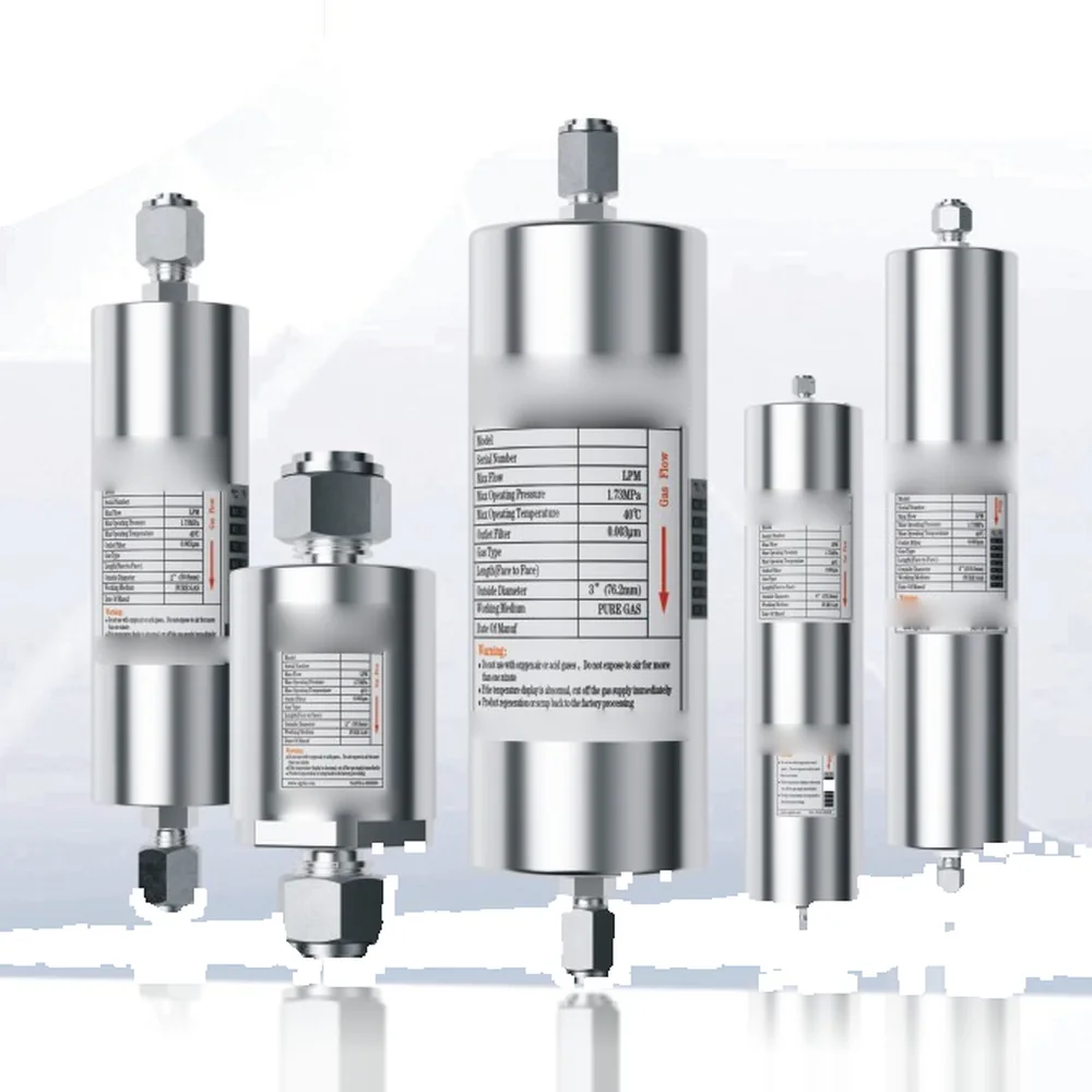
Gas Purifiers
POU Ambient-Temperature Gas Purifier
Product Overview
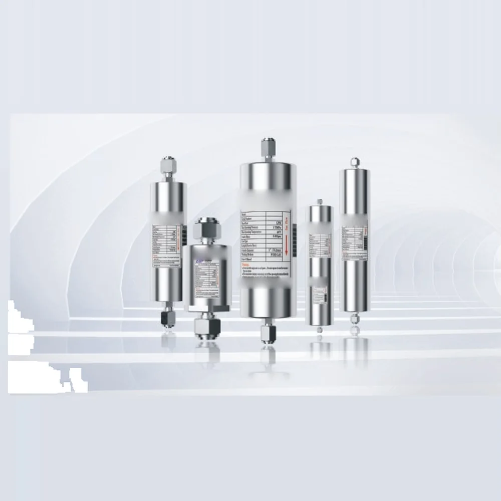
An inline purifier installed at the point of use, removing trace impurities by catalytic adsorption at ambient temperature and pressure, with outlet purity down to ppb level. Flow covers 5–4000 SLPM, and the fitting size, vessel length and panel configuration can all be customised to site requirements.
Features & Specifications
Standard POU selection table
| Model | Max. flow (SLPM) | Nominal flow (SLPM) | Max. operating pressure (MPa) | Connection type | Length OAL (face to face) | Tube OD (mm) |
|---|---|---|---|---|---|---|
| BSP005 | 5 | 0.5 | 6.9 | 1/4"MVCR | 84.1 (3.31"±.03) | 38.1 (1.5") |
| BSP010 | 10 | 1.5 | 6.9 | 1/4"MVCR | 127 (5.00"±.03) | 38.1 (1.5") |
| BSP010A | 10 | 1.5 | 6.9 | 1/4"MVCR | 114.3 (4.50"±.03) | 38.1 (1.5") |
| BSP050 | 50 | 5 | 1.73 | 1/4"MVCR | 208.3 (8.20"±.03) | 50.8 (2.0") |
| BSP050A | 50 | 5 | 1.73 | 1/4"MVCR | 160 (6.30"±.03) | 50.8 (2.0") |
| BSP060 | 60 | 9 | 1.73 | 1/4"MVCR | 208.3 (8.20"±.03) | 76.2 (3.0") |
| BSP075 | 75 | 10 | 1.73 | 1/4"MVCR | 201.7 (7.94"±.03) | 76.2 (3.0") |
| BSP100 | 100 | 12 | 1.73 | 1/4"MVCR | 317.5 (12.50"±.03) | 50.8 (2.0") |
| BSP120 | 120 | 25 | 1.73 | 1/4"MVCR | 254 (10.00"±.03) | 76.2 (3.0") |
| BSP250 | 250 | 40 | 1.73 | 1/2"MVCR | 462.28 (18.20"±.03) | 76.2 (3.0") |
| BSP300 | 300 | 80 | 1.73 | 1/2"MVCR | 439.42 (17.3"±.06) | 101.6 (4.0") |
| BSP500 | 500 | 80 | 1.73 | 1/2"MVCR | 508 (20.00"±.06) | 101.6 (4.0") |
| BSP800 | 800 | 200 | 1.73 | 1/2"MVCR | 702 (27.64"±.06) | 152.4 (6.0") |
| BSP1000 | 1000 | 300 | 1.73 | 1/2"MVCR | 999.24 (39.34"±.06) | 152.4 (6.0") |
| BSP1500 | 1500 | 400 | 1.73 | 3/4"MVCR | 1134.4 (44.66"±.06) | 152.4 (6.0") |
| BSP2000 | 2000 | 1000 | 1.73 | 3/4"MVCR | 1290.32 (50.8"±.06) | 152.4 (6.0") |
| BSP2500 | 2500 | 1100 | 1.73 | 1"MVCR | 1302.4 (51.28"±.06) | 152.4 (6.0") |
| BSP4000 | 4000 | 2000 | 1.73 | 1"VCR | Combined panel | Combined panel |
The table lists the specification and configuration of standard models only; please enquire for other special requirements.



Detailed Description
Working principle
The P series uses catalytic adsorption to hold impurities from the feed gas on the surface of the adsorbent at ambient temperature. Because no heating and no purge gas are required, the unit is compact and cheap to install, which suits mounting directly at the point of use ahead of process equipment. "Ambient temperature and pressure" refers to the purification mechanism not being driven by heat — it does not mean the vessel only withstands atmospheric pressure. Standard models are rated between 1.73 and 6.9 MPa; where higher pressure is needed, see the high-pressure version (BSP-HP).Product features
・Returned to the factory for regeneration every 1–2 years, with an equipment life of over 20 years ・Built-in high-precision filter with a filtration rating of 0.003 μm ・Flow options from 5 to 4000 SLPM ・With a source gas quality of 5N or better, removes H₂O, O₂, CO, CO₂, H₂ and NMHC to < 1 ppb; removal of acids, bases and refractory compounds is also available ・Fitting size, vessel length and panel configuration are all customisableApplicable gases
N₂, H₂, O₂, Ar, He, Kr, Ne, Xe, CDA, CH₄, CO₂, Cl₂, BF₃, HCl, GeCl₄, GeH₄, H₂S, H₂Se, HBr, SiHCl₃, SO₂ and more than thirty other specialty gases.Processes and industries served
The value of a POU purifier lies in the last mile. On its way from the facility supply to the tool, bulk gas passes through tens or hundreds of metres of piping, valves and fittings, and outgassing, micro-leaks and dead-leg residue along that route recontaminate gas that left the source perfectly clean. Installing a purifier at the tool inlet is the final chance to intercept impurities before they enter the process chamber. ・Semiconductor front end: carrier and purge gas for epitaxy, etch, CVD and ALD ・Compound semiconductor and LED: MOCVD carrier gas and specialty gas lines ・Display and panel: inert gas protection in evaporation and packaging processes ・Analytical laboratories: carrier and fuel gas for GC, GC-MS and ICP-MS, preventing baseline drift and ghost peaks ・Optical fibre and advanced materials: protective gas for preform deposition and drawing furnacesInstallation and layout notes
・Mount as close to the point of use as possible: the longer the run between purifier and tool, the more opportunity there is for recontamination ・Provide particulate filtration upstream: the purifier has a 0.003 μm filter built in, but if the source gas carries dust or oil mist, add pre-filtration so the adsorbent does not fail prematurely ・Fit a bypass and isolation valves: replacement or factory regeneration then does not stop the line ・Do not reverse the inlet and outlet: the vessel is marked with the flow direction, and reversing it feeds fresh gas into the saturated end of the bed ・Purge with purified gas after installation: air and moisture that entered during pipework must be driven out first, otherwise outlet quality will not meet target in the first hours of operation ・No electrical power and no purge gas are required, which is where this series saves the most on installation compared with heated and fully automatic typesMaintenance and regeneration
・Under normal source conditions the factory regeneration interval is 1–2 years; actual life depends on impurity concentration and actual gas consumption ・A saturated adsorbent must not be opened or discarded on site — the whole cartridge is returned for processing ・Fit an online analyser (moisture or oxygen) at the outlet, or arrange periodic sampling; judging replacement from measured data is far more accurate than counting service hours ・On-site instruments can read outlet H₂O concentrations in CDA and N₂ down to the 0.001–0.006 ppbV range, which serves as a reference baseline for acceptance and routine monitoringChoosing between neighbouring models
| Model | Flow | Power needed | Removes CH₄ / N₂ | Typical use |
|---|---|---|---|---|
| BSP (this model) | 5–4000 SLPM | No | No | Point of use at the tool |
| BSP-HP | 100–1000 SLPM | No | No | Direct high-pressure cylinder supply, purification before regulation |
| BSH heated type | 0.2–150 LPM | Yes | Yes | Small flow with deep removal required |
| BSS14 large-flow ambient | 100–5000 Nm³/h | No | No | Temporary or standby supply at facility level |
Purifiable gases and outlet purity
Different gas and impurity combinations call for different adsorbent formulations; please provide the gas type, flow rate and required outlet quality together when specifying.| Formulation | Applicable gases | Impurities removed and outlet purity |
|---|---|---|
| 51 | AsH₃, PH₃ | H₂O < 1 ppbV; O₂ < 1 ppbV; metals < 1 ppbV |
| 23 | CDA, O₂, N₂, Ar, He, Kr, Ne, Xe, H₂, D₂, N₂O, NO, CF₄ | H₂O < 100 pptV; CO₂ < 100 pptV; volatile acids < 1 pptV; volatile bases < 1 pptV; organics < 1 pptV; refractory compounds < 5 pptV; metals < 1 ppbV |
| 44 | CDA, O₂, N₂, Ar, He, Ne, Kr, Xe, H₂, CO₂, C₂H₆, C₃H₈, C₄H₁₀, C₂H₂, C₃H₆, C₂H₄, NH₃ | Condensable organics (>C6) < 1 pptV; non-condensable organics (>C3) < 5 pptV; refractory compounds (as HMDSO) < 1 pptV; C₃H₇NO (DMF) < 100 pptV |
| 48 | CDA, O₂, N₂, Ar, He, Ne, Kr, Xe | H₂O < 100 pptV; condensable organics (as toluene) < 1 pptV; non-condensable organics (as butane) < 5 pptV; refractory compounds (as HMDSO) < 1 pptV; volatile acids (as SO₂) < 1 pptV; volatile bases (as NH₃) < 10 pptV |
| 84 | CO₂ | H₂O < 1 ppbV; O₂ < 200 pptV; volatile acids < 1 pptV; volatile bases < 1 pptV; refractory compounds < 1 pptV; condensable organics < 1 pptV |
| 62 | CO | H₂O < 1 ppbV; O₂ < 1 ppbV; CO₂ < 1 ppbV |
| 61 | HBr | H₂O < 1 ppbV |
| 32 | B₂H₆, BCl₃, CClH₃, GeCl₄, GeH₄, H₂S, H₂Se, NF₃, SiCl₄, SiF₄, SiH₂Cl₂, SiHCl₃, SO₂, CHClF₂, BF₃ | H₂O < 1 ppbV; metals < 1 ppbV |
| 60 | HCl, Cl₂ | Hydrocarbons (as toluene) < 1 pptV; Fe / Ni / Mo / Cr / Mn < 14 pptV; H₂O < 15 ppbV |
| 22 | CDA, O₂, CO₂, N₂, Ar, He, Ne, Kr, Xe, H₂, D₂, NH₃, AsH₃, PH₃, GeH₄, SiH₄, N₂O, NO, CF₄, C₂H₂, (CH₃)₂NH (DMA), (CH₃)₂N₂H₂ (DMHz) | H₂O < 100 pptV |
| 94 | H₂, N₂, Ar, He, Ne, Kr, Xe, H₂/N₂, H₂/inert gas mixtures | H₂O < 100 pptV; CO₂ < 100 pptV; O₂ < 250 pptV; CO < 1 ppbV; volatile acids (as SO₂) < 1 pptV; volatile bases (as NH₃) < 10 pptV; CxHy (45–100 amu) < 10 pptV; CxHy (>100 amu) < 1 pptV; refractory compounds (as HMDSO) < 1 pptV |
| 43 | N₂, Ar, He, Kr, Ne, Xe, H₂, CDA, O₂, CO₂ | Volatile acids < 1 pptV; volatile bases < 5 pptV; organics < 1 pptV; refractory compounds < 1 pptV; metals < 1 ppbV |
| 99 | H₂, O₂, N₂, Ar, He, Ne, Kr, Xe, H₂/N₂, H₂/inert gas mixtures | H₂O, O₂, CO and CO₂ all < 100 pptV |
| 95 | N₂, Ar, He, Kr, Ne, Xe, CF₄, CH₄, C₂H₆, C₃H₈, C₄H₁₀ | H₂O, O₂, CO, CO₂ and H₂ all < 100 pptV; sulphur compounds < 1 ppbV |
| 72 | NH₃, C₂H₄, GeH₄, CSiH₆, C₂H₇N, C₃H₆, SF₆, H₂/SiH₄ mixtures, C₂H₈N₂, CH₃SiH₃, H₂/SiH₄ mixtures | H₂O, O₂ and CO₂ all < 1 ppb; organics (>C4) < 1 ppb; metals < 1 ppb |
| 82 | SiH₄ | H₂O, CO₂, O₂, CO and sulphur compounds all < 1 ppb; metals removed to < 1 ppb |