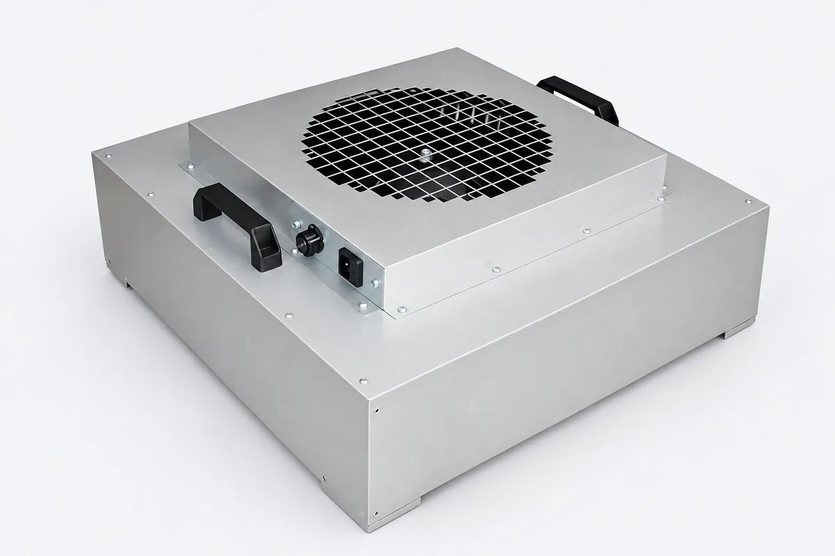
FFU Fan Filter Unit
Product Overview
Key Specifications
- Filtration Efficiency
- ≥99.99–99.999% @ 0.3 μm (per the HEPA / ULPA filter fitted)
- Fan Type
- Imported external-rotor centrifugal fan, 80 W motor
- Power Supply
- AC 220~240V 50Hz
- Control
- Three-speed control (high / medium / low); connectable to an FFU group control system (32 channels per hub)



Specifications
- Body Material
- Aluminum-zinc coated steel / stainless steel / painted cold-rolled steel / polypropylene
- Structure
- Dry-seal or liquid-seal FFU; impeller in aluminum, stainless steel or nylon
- Filtration Efficiency
- ≥99.99–99.999% @ 0.3 μm (per the HEPA / ULPA filter fitted)
- Fan Type
- Imported external-rotor centrifugal fan, 80 W motor
- Power Supply
- AC 220~240V 50Hz
- Control
- Three-speed control (high / medium / low); connectable to an FFU group control system (32 channels per hub)
Model Reference
| Model | Module Size (mm) | Filter Size (mm) | Airflow (m³/min) | Face Velocity (m/s) | Current Draw (A) | Noise (dB) |
|---|---|---|---|---|---|---|
| 4′×4′ | 1175×1175×320 | 1170×1170×70 | 45 | 0.55 | 1.3 | ≤58 |
| 2′×4′ | 1175×575×320 | 1170×570×70 | 18 | 0.45 | 1.0 | ≤52 |
| 2′×2′ | 575×575×320 | 570×570×70 | 6.8 | 0.35 | 0.8 | ≤46 |
Airflow is calculated as face velocity × filter area; actual airflow varies with external static pressure and the filter grade fitted
Detailed Description
Self-powered, with the plenum under negative pressure
Once conventional ducted supply is built, the outlet positions are fixed, and reconfiguring the production line means altering ductwork. An FFU puts the fan inside the module, so each unit is an independent supply unit: install it wherever air is needed, and when the line is reconfigured, take it down and move it without touching the ceiling grid. When running, FFUs draw the plenum above them to a negative pressure relative to the clean area. If the plenum has gaps, air leaks from the clean area into the plenum, rather than dust accumulated in the plenum being pushed into the clean area. A positive-pressure ducted system is the opposite: if the joints are poorly made, particles accumulated inside the duct are pushed out by the pressure.The face velocity in the datasheet is not the velocity at the working position
The frequently quoted 0.36–0.54 m/s comes from EU GMP Annex 1 (2022) §4.30. It is a guidance value for Grade A unidirectional flow at the working position, and deviations can be justified scientifically in the contamination control strategy (CCS); the US FDA 2004 aseptic processing guidance recommends 0.45 m/s (90 fpm) ±20%. Both are requirements for the clean area, not FFU product specifications. The velocity at the filter outlet face changes on its way down to working height, affected by FFU ceiling coverage, return air locations and obstruction by equipment. The number of units and their speed should therefore be set from the velocity and uniformity measured at the working position, rather than taking the face velocity in the datasheet as the acceptance value.What data to look at for comparison and acceptance
IEST-RP-CC036.1 lists the test items for FFUs: airflow, power consumption, external static pressure, noise, outlet velocity uniformity and vibration; the Chinese product standard is JG/T 388-2012 (Fan Filter Units). When comparing FFUs from two suppliers, airflow and power consumption must be compared at the same external static pressure, otherwise the figures are meaningless. With a ULPA filter the filter resistance is higher and the airflow the same fan can deliver drops, so selection should be confirmed with the filter grade actually fitted.Dry type and gel-seal type
A dry FFU is sealed with a gasket; it is quick to install and low in cost, and is the approach used in most electronics facilities. The gel-seal type has a gel channel running around the ceiling grid, into which the knife edge of the filter frame is inserted to form a continuous sealing surface. It suits pharmaceutical and high-grade clean areas where filters are leak-tested after installation and retested periodically, at the cost of a more complex grid system.Group control: how to manage hundreds of FFUs
A single cleanroom can easily contain hundreds of FFUs. The group control system consists of one-to-two smart control units, hubs (each taking 32 channels), an FFU control host, centralised PC monitoring and a low-voltage control cabinet; speed can be regulated by capacitor, transformer voltage regulation or motor taps. Functions include zoned start/stop, centralised speed control, fault alarms and history records; when the PC is shut down, the control host can still carry out round-the-clock monitoring on its own. It brings three things: scheduled turndown, dropping to low speed outside production hours without sending someone up a ladder; visible faults, where a single stopped unit triggers an alarm that pinpoints its location instead of being found only when a cleanliness test fails; and traceability, where history records allow the airflow conditions during production of a given batch to be retrieved. Communication and power cables all run in the ceiling void, so zones, hub locations and the control cabinet position must be decided before the ceiling grid is installed; pulling cables afterwards costs much more.Frequently Asked Questions
Does an FFU face velocity of 0.45 m/s meet the GMP Grade A requirement?
The two cannot simply be equated. The 0.36–0.54 m/s in EU GMP Annex 1 (2022) §4.30 and the 0.45 m/s ±20% in FDA 2004 both refer to the velocity of Grade A unidirectional flow at the working position, not the specification value at the FFU filter outlet face. The airflow from the same FFU is affected on its way to working height by ceiling coverage, return air locations and obstruction by equipment. Confirm using the velocity and uniformity measured at the working position, then go back and adjust the number of FFUs and their speed settings.
How many FFUs can one hub in a group control system take? Does it stop if the PC is shut down?
Each hub takes 32 channels, expanded with one-to-two smart control units; facilities with hundreds of units or more connect multiple hubs, zone by zone, to the FFU control host. The PC only handles centralised monitoring and records; the control host itself can operate independently, so with the PC shut down it still maintains round-the-clock monitoring and alarms and the units do not stop. The number of zones, units per zone and hub locations should be finalised before the ceiling grid is installed.
What should I watch for when comparing the airflow and power consumption of two FFU suppliers?
Compare them at the same external static pressure. FFU airflow drops as external static pressure and filter resistance rise; if one supplier states airflow at 0 Pa and the other under load, the figures look very different but cannot actually be compared. The test items in IEST-RP-CC036.1 include airflow, power consumption, external static pressure, noise, velocity uniformity and vibration, and when requesting a quotation you can ask for test data at a specified static pressure and a specified filter grade.
Selection References
Before ordering, verify the efficiency grade, media type, and whether the operating environment fits your requirements.