Cleanroom Equipment
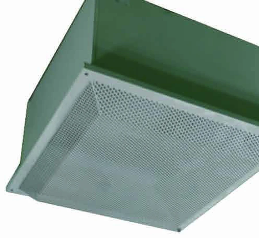
HEPA Diffuser Box
Product Overview
A HEPA diffuser box combines the filter, a plenum and a diffuser plate into a single ceiling-mounted terminal that connects to ductwork as the final filtration stage of a cleanroom. Unlike an FFU it has no fan of its own — air is supplied by the central air handling unit — so the construction is simple, with no motor noise and no motor life to manage.
The filter is bottom-loaded and can be changed from inside the room without entering the ceiling void. Top-entry and side-entry duct connections are both available; the side-entry version saves installation height where clearance below beams is tight.
Key Specifications
- Filtration Efficiency
- ≥ 99.99%(≥0.3μm 塵粒)
- Rated Airflow
- Rated airflow = model number × 100 m³/h (500–3,000 m³/h)
- Initial Pressure Drop
- ≤ 230 Pa
- Mounting Orientation
- Bottom-loading filter — replaceable from inside the room



Specifications
- Structure
- Inlet orientation I = top entry, II = side entry. Standard diffuser plate; a diffusing mesh plate is available (model suffix GKF)
- Filtration Efficiency
- ≥ 99.99%(≥0.3μm 塵粒)
- Rated Airflow
- Rated airflow = model number × 100 m³/h (500–3,000 m³/h)
- Mounting Orientation
- Bottom-loading filter — replaceable from inside the room
Model Reference
| Top-entry Model | Side-entry Model | Rated Airflow (m³/h) | Filter Size (mm) | Overall K×L×H/h (mm) | Duct Flange A×B (mm) | Ceiling Cutout (mm) | Weight (kg) |
|---|---|---|---|---|---|---|---|
| c.05 I | c.02 II | 500 | 320×320×90 | 370×370×360/480 | 200×200 | 380×380 | 20 |
| c.10 I | c.10 II | 1000 | 610×610×69 | 660×660×360/480 | 320×200 | 670×670 | 36 |
| c.15 I | c.15 II | 1500 | 915×610×69 | 965×660×360/480 | 500×250 | 975×670 | 43 |
| c.20 I | c.20 II | 2000 | 1220×610×69 | 1270×660×360/480 | 630×250 | 1280×670 | 53 |
| c.25 I | c.25 II | 2500 | 1220×610×80 | 1270×660×360/480 | 630×250 | 1280×670 | 60 |
| c.30 I | c.30 II | 3000 | 1260×630×90 | 1310×680×360/480 | 630×250 | 1320×690 | 65 |
Detailed Description
When to use a diffuser box and when to use an FFU
Both are cleanroom supply terminals; the difference is where the fan sits. A diffuser box is fed by the central air handler, so the terminal contains only a filter and a diffuser plate. Fewer devices, fewer moving parts, and no hundreds of motors above the ceiling to maintain, which keeps long-term maintenance cost low. The trade-off is that airflow distribution depends on ducts and dampers, so layout changes mean duct work. An FFU distributes fans to every terminal, making layout changes easy at the price of a motor at each point. For turbulent-flow cleanrooms, localised clean zones, or existing plants where AHU static pressure is already stretched, the diffuser box is usually the more sensible choice.Choosing top entry or side entry
The top-entry type (I) connects above the box, giving the shortest air path and the lowest resistance. It is the default, provided the ceiling void is deep enough for the duct elbow. The side-entry type (II) connects from the side and needs no elbow clearance above the box, which suits retrofits with tight headroom below beams. At the same airflow the air makes one more turn inside the box, so uniformity is slightly below the top-entry version and depends more on the diffuser plate to spread the flow.Initial resistance and when to change the filter
Initial resistance as supplied is ≤230Pa. Common practice is to replace at twice the initial value — that is, when the differential pressure reaches roughly 460Pa. Fit a differential pressure gauge or leave a measuring port at the terminal and judge by measured pressure rather than months in service. The same filter may reach final resistance within six months in a dusty environment and still show little rise after two years in a clean one. Replacing on a calendar produces both kinds of waste at once: filters discarded with life left, and filters left in long past their limit.Selection References
Before ordering, verify the efficiency grade, media type, and whether the operating environment fits your requirements.