제산 AMC 이온교환 케미컬 필터 - 활성탄 케미컬 필터 | Baisheng Tech
품번ion-exchange-acid-filter활성탄 케미컬 필터이온교환 케미컬 필터
활성탄 케미컬 필터

제산 AMC 이온교환 케미컬 필터

제품 개요

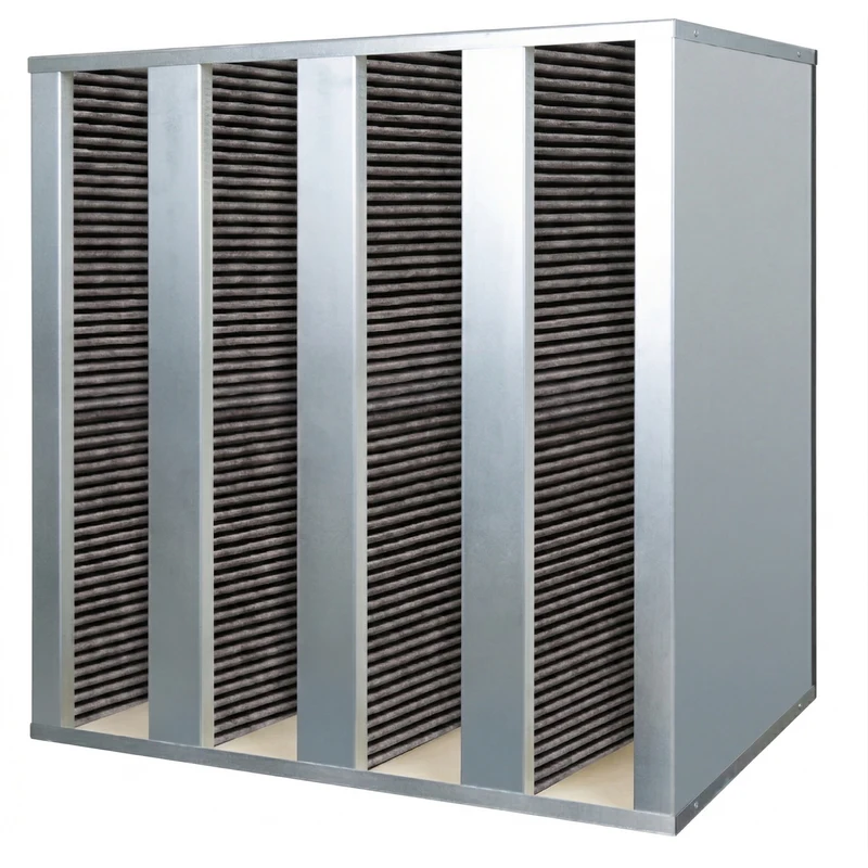
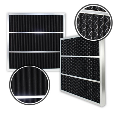
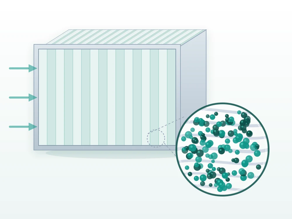
Baisheng의 제산 AMC 이온교환 케미컬 필터는 음이온 관능화 수지를 흡착 주체로 삼는 기체상 오염물질 필터로, 반도체와 광전자 공장 안의 산성 분자 오염(AMC)을 겨냥합니다. 불화수소, 염산, 질산, 브롬화수소산, 황산, 이산화황 같은 강산과 아세트산, 폼산, 아질산 같은 약산이 대상입니다. 시중의 이온교환 여재는 대부분 제알칼리용(양이온형, 암모니아와 아민류 처리)입니다. 본 시리즈는 반대 방향입니다. 수지 말단에 붙은 것이 음이온 관능기라서 양성자산과만 반응하고 염기류에는 전혀 작용하지 않습니다. 활성탄과의 가장 큰 차이는 무엇을 흡착하지 않는가에 있습니다. 활성탄은 미세공의 물리 흡착에 기대므로 공극이 휘발성 유기물, 에스터, 질소산화물을 가리지 않고 받아들여 산을 만나기도 전에 용량의 상당 부분을 나눠 써 버립니다. 이온교환 수지의 골격은 불활성 폴리스티렌/디비닐벤젠으로 흡착 공극이 없고 관능기만 작용하므로 용량이 처음부터 끝까지 산에만 쓰입니다. 체적 교환 용량은 함침 활성탄의 약 네 배입니다. 여재는 두 가지 구조 중에서 고를 수 있습니다. **복합 플리츠형**은 약 0.5 mm 수지 입자를 섬유 구조에 박아 넣고 주름을 잡은 것으로, 여재 면적이 펼쳐져 압력손실이 낮으므로 송풍기 여유가 빠듯한 곳에 알맞습니다. **발포체형**은 수지 구슬을 개방형 폴리우레탄 발포체 골격에 고정한 것으로, 단위 부피당 흡착제를 더 많이 담을 수 있어 수명이 깁니다. 두 구조 모두 수용성 산액 함침을 쓰지 않아 스며 나오거나 가스를 내뿜을 위험이 없습니다. 수지가 담체 안에 고정되어 있어 운전 중에 마모되어 가루가 날리지 않으므로, HEPA/ULPA 앞뒤에 바로 이어 붙여도 막힘이나 미립자 방출을 걱정할 필요가 없습니다. 외곽 프레임은 아노다이징 알루미늄이며 치수는 클린룸에서 흔히 쓰는 FFU와 필터 프레임에 맞추었으므로 대부분의 현장에서 기존 필터를 그대로 교체할 수 있습니다.

제품 특성

►**Target contaminants, strong acids**: hydrogen fluoride HF, hydrogen chloride HCl, nitric acid HNO₃, hydrogen bromide HBr, sulphuric acid H₂SO₄, sulphur dioxide SO₂ ►**Target contaminants, weak acids**: acetic acid, formic acid, nitrous acid HNO₂ ►**Deliberately not addressed**: ammonia and amines, nitrogen oxides NOx, volatile organics and esters, ozone, chlorine, organophosphate dopants ►**Media base**: porous polystyrene/divinylbenzene polymer, anion-functionalised at the chain ends; inert backbone, no adsorption pores, no aqueous acid impregnation ►**Media construction**: pleated composite (resin particles embedded in a fibrous structure, then pleated) or foam (resin beads fixed on open-cell polyurethane) ►**Volumetric exchange capacity**: roughly four times that of impregnated activated carbon, in equivalents per litre ►**Secondary emission**: none — stores no nitrogen oxides, releases no weak acid as pH falls, generates no acetic acid from ester cleavage ►**Frame material**: anodised aluminium ►**Recommended operating conditions**: temperature ≤ 40 °C, relative humidity 30 – 60 % ►**Initial SO₂ removal efficiency**: 97.4 % for 128 mm pleated composite and for foam; ≥ 95 % for 68 mm pleated composite

Pleated composite specifications

DepthFrame size H×WMedia areaSorbent net weightTotal weightRated airflowRated pressure drop
68 mm800×485 mm4.75 m²2.68 kg4.16 kg1,000 m³/h12.9 Pa
68 mm742×742 mm7.04 m²3.77 kg5.85 kg1,420 m³/h12.9 Pa
68 mm800×690 mm7.04 m²3.77 kg5.85 kg1,420 m³/h12.9 Pa
128 mm800×485 mm9.51 m²5.25 kg8.23 kg1,000 m³/h19.8 Pa
128 mm742×742 mm13.98 m²7.53 kg11.69 kg1,420 m³/h19.8 Pa
128 mm800×690 mm13.98 m²7.53 kg11.69 kg1,420 m³/h19.8 Pa

Foam specifications

DepthFrame size H×WSorbent net weightTotal weightRated airflowRated pressure drop
48 mm800×690 mm3.37 kg5.06 kg1,420 m³/h20.8 Pa
48 mm800×485 mm2.38 kg3.57 kg1,000 m³/h20.8 Pa
68 mm800×690 mm4.96 kg7.53 kg1,420 m³/h31.6 Pa
68 mm800×485 mm3.47 kg5.35 kg1,000 m³/h31.6 Pa
88 mm800×690 mm6.64 kg12.00 kg1,420 m³/h42.5 Pa
88 mm800×485 mm4.66 kg8.43 kg1,000 m³/h42.5 Pa
Every rated airflow corresponds to a face velocity of 0.71 m/s. Non-standard sizes and other depths are built to site conditions.
견적 문의

Email:sales@baisheng-tech.com

전화+886-2-2598-1958

상세 설명

Why acidic AMC has to be handled separately from activated carbon

Almost every acid that causes defects in semiconductor manufacturing is an H-X protic acid, one that donates a proton; Lewis acids can be set aside in practice. What they have in common is that they are reactive, corrosive, form salt crystals on contact with bases, and have a low dissociation constant — which is to say they are strong. The awkward ones are the acid precursors: not acids themselves, but substances that turn into acids on a surface once they take up water. - **Sulphur dioxide** forms sulphurous acid with water and then oxidises to sulphuric acid. Fast and strongly acidic, it is the most active precursor of the group. - **Nitrogen dioxide** forms nitrous and nitric acid with water. Less efficient, but it keeps happening. - **PGMEA**, the standard solvent in the lithography area, hydrolyses into PGME and acetic acid. This is a latent precursor — it may not act until it is already inside the filter. Note that hydrogen sulphide and the nitrogen oxides are not acids in themselves. Counting them toward a total-acid figure blurs the question that matters: which specific acid does this process, on this tool, need protecting from — not how many anions an impinger can be made to show. Where the acids come from is often misread too. Ambient outdoor air carries very little acid, and precursor levels are broadly falling, volcanic activity and biomass burning aside; levels around a plant may be raised by nearby stack emissions. But the bulk of the load originates inside the fab: hydrogen halides from wet etch, nitrogen compounds from dry etch, and ester solvents from the lithography area.

How the two media differ mechanically

**Activated carbon** is a microporous carbon material, usually made from natural organic feedstock or coal, and not a clean, inert graphite structure. In impregnated grades the pores serve only as a carrier for the treatment chemistry. Three side effects follow unavoidably: - Physical adsorption always occurs, so volatile organics and esters will be taken in - Redox reactions always occur at the surface, so nitrogen oxides are converted and stored - Adsorption is reversible, so incoming strong acids displace weak acids already held, most visibly as pH falls **Ion exchange resin** is a porous polystyrene/divinylbenzene polymer with anionic functional groups at the chain ends. The backbone itself is clean and inert, and the functional groups are evenly distributed — unlike impregnated carbon, where the chemistry is coated onto the pore walls and its concentration varies with pore size. The characteristics are the mirror image: - No adsorption pores, so esters and volatile organics are not physically adsorbed - No redox activity inside the pore and sorption system, so nitrogen oxides are not stored - Acids bind chemically to the functional groups and are not released back into the airstream when conditions change

What selectivity buys you

How each protection target shifts on ion exchange media

Relative performance (0–100) of the same targets on two media types

Activated carbonIon exchange8784598393805195Strong acid corrosion96Weak acid corrosion83Spill peak resilience89BF₃ formation98Boranes / borates14NOx interception17VOC / ester capture9Chlorine / ozone11Relative performance
Acid targets, mean
80 → 92
Non-targets, mean
78 → 13
Separation
2 → 79

Acid targets move up while every non-target drops to the floor — by design, not by defect. Activated carbon pores take in everything, so capacity is shared with organics and nitrogen oxides; on ion exchange resin only the anionic functional groups react, leaving the whole capacity for acids. The trade-off is that ammonia, chlorine, ozone and organophosphate dopants are not addressed at all, so sites that must control those still need carbon alongside.

Most acid-related defect risks are tied to a particular process step or a particular tool, and rarely to total acids at all. In the majority of cases a strongly selective filter therefore delivers both the best performance and the best total cost of ownership. Media marketed as all-round rarely come out ahead, and they always carry a proportional risk of side reactions and ageing reactions.

Service life in the field

Strong-acid removal efficiency across 60 months in service

FFU-mounted ion exchange filter, tested with a strong-acid mixture

025507510094.3%New88.1%30 months85.8%"60 months"8.5Months in serviceStrong-acid removal (%)
Cleanroom HF target
< 0.1
ppbv
HF measured
< 0.03
ppbv
Boron level
50% of target

Efficiency falls only 8.5 percentage points over five years, and the reason is what the medium refuses to take in. Over the same period an activated carbon bed has already given most of its capacity to organics and nitrogen oxides, leaving little for acids. In the field this translates to hydrogen fluoride held below a third of the cleanroom target, with boron from the BF₃ by-product at half the target value.

Media construction: choosing between pleated composite and foam

The resin is the same; the carrier is not, and carrier construction pushes pressure drop and service life in opposite directions. The two charts in this section have to be read together — either one alone leads to the wrong choice. **Pressure drop**: pleating opens the media out to several square metres of effective area, so the air actually passes through the medium far more slowly than the face velocity suggests. Foam is a flat panel whose frontal area is simply the frame area.

Initial pressure drop across the five media configurations

One face-velocity scale, three operating points: 0.5 / 0.71 (rated) / 1.0 m/s

0.5 m/s0.71 m/s rated1.0 m/s0204060Pleated composite 68 mm12.921Pleated composite 128 mm19.832Foam 48 mm20.832Foam 68 mm31.649Foam 88 mm42.566Pleated compositeFoamInitial pressure drop (Pa)
Same 68 mm
12.9 vs 31.6
Lowest
12.9 Pa
Highest
42.5 Pa

At the same 68 mm depth, the pleated composite runs at four tenths the pressure drop of the foam — pleating spreads the media out to 7.1 m², whereas foam is a flat panel whose frontal area is simply the frame area. Depth alone therefore says nothing about pressure drop; it has to be read together with construction. What the foam buys in return is more sorbent per unit volume and a longer life: two ends of the same trade-off. A 40% rise in face velocity costs roughly 60% more pressure drop, so bringing face velocity down by moving up a frame size often saves more fan power than changing media.

**Service life**: foam stacks resin beads on a skeleton, so at the same depth it holds more sorbent than resin embedded in fibre, which gives it the higher dose capacity.

Service life of the five media configurations, expressed as cumulative dose

Horizontal axis is cumulative SO₂ dose; the two constructions were tested at different concentrations, so only dose is comparable

Efficiency ≥ 95%95% → 50%50% → spent05k10k15kPleated composite 68 mm6.9kPleated composite 128 mm11.9kFoam 48 mm9.2kFoam 68 mm12.9kFoam 88 mm16.6kPleated compositeFoamCumulative SO₂ dose (ppbv·days)050010001500Equivalent days at 10 ppbv
Life ratio at 68 mm
1 : 2.1
Pleated 128 mm
871 days
Foam 88 mm
1,290 days

Converting days into dose — concentration multiplied by time — is what puts the two constructions on the same ruler. It is also the IRDS position on AMC: there is no critical concentration, only a dose. Translated back to a site at 10 ppbv, the 128 mm pleated composite lasts around 871 days and the 88 mm foam around 1,290. Read alongside the pressure chart, the trade-off is complete: at the same 68 mm, the pleated composite costs four tenths the pressure drop but delivers half the life, because foam packs more sorbent into the same volume. Choose pleated when fan power is tight, foam when change-out labour is expensive.

Together the two charts are the whole trade-off. At 68 mm, the pleated composite costs four tenths the pressure drop of the foam but carries roughly half the dose capacity. The decision points are straightforward: - **Fan headroom is tight, or this stage already sits in series with HEPA/ULPA** — take the pleated composite and keep the pressure budget for the particulate stage - **Change-out means downtime, or the position is awkward to reach (in a ceiling plenum, on top of a tool)** — take the foam and buy service life with volume - **Both are tight** — look at frame size first. A forty per cent rise in face velocity costs roughly sixty per cent more pressure drop, so moving up a frame size to bring face velocity down usually beats changing media

Case one: wafer transport FFU, 28 months

One fab, one airstream, a batch of each medium installed side by side and removed after 28 months for media analysis and efficiency re-testing.

What the media had accumulated after 28 months

Wafer transport FFU filters, post-removal analysis, grams

Activated carbon200 gTo scale: total load13%23%65%Normalised: compositionIon exchange20 gTo scale: total load75%20%Normalised: compositionAcidsNitrogen oxidesOrganics
Total load
200 → 20 g
Acid share
13% → 75%
Non-target load
174 → 5 g

On the carbon filter 87% of what was captured has nothing to do with acids — organics and nitrogen oxides fill the pores first, leaving just 26 g of capacity actually spent on acids. Ion exchange resin has no adsorption pores; only the anionic functional groups react, so total load is a tenth as large and three quarters of it is acid. That is where the service-life gap comes from at identical size and airflow: not from capturing more, but from not spending capacity on things it was never meant to capture.

Efficiency loss across a concentration spike

Filters already 28 months in service, sulphur dioxide inlet at 20 ppbv

0255075100Before spikeAfter spikeActivated carbon51.470.218.8Ion exchange66.379.813.5Sulphur dioxide removal (%)
Gap before
+9.6
Gap after
+14.9
Points lost
18.8 vs 13.5

Spikes are the real test for a chemical filter — a process leak, a neighbouring stack, a seasonal shift in outdoor air can raise concentration by an order of magnitude within hours. Activated carbon loses 18.8 percentage points because stronger acids displace what the pores already held, so efficiency bleeds from both ends. Ion exchange binds chemically and has no displacement mechanism, losing only 13.5 points — its post-spike 66.3% is almost level with where the carbon filter stood before the spike, at 70.2%.

Case two: coater and developer inlet, five years

After five years, is the filter absorbing acetic acid or releasing it?

Coater/developer temperature-humidity inlet filter, acetic acid inlet at 4 ppbv

Net removalNet emission-5-2.502.55NewAfter 5 yearsAfter 5 h purge+3.87-4.14-0.51Activated carbon+3.92+0.09+0.09Ion exchangeOperating stageAcetic acid (ppbv)
Acetic acid inlet
4
ppbv
Carbon at 5 years
−4.14
ppbv
Ion exchange at 5 years
+0.09
ppbv

Activated carbon draws the process solvent PGMEA into its pores, where prolonged heat and humidity hydrolyse it, splitting off acetic acid that is then released downstream — the filter turns from a barrier into a source, measured at a net emission of 4.14 ppbv that attacks the chiller heat exchanger directly. Five hours of clean-air purging only brings the release down to 0.51 ppbv, which means the acetic acid is not surface residue but is still being generated. Ion exchange resin has no adsorption pores and does not take up esters, so there is nothing stored to cleave; after five years it is still removing.

This case deserves particular attention, because the failure mode is the opposite of what most people expect: the filter had not stopped absorbing — it had started emitting. The inlet filter on the temperature and humidity control section was carbon-based; after years of taking up PGMEA from the lithography area, heat and humidity hydrolysed it, cleaving off acetic acid that was then released downstream, attacking the chiller heat exchanger directly. A differential pressure gauge sees none of this — pressure drop does not change because of a chemical reaction. The only way to catch it is outlet sampling.

Case three: reticle and bare reticle stockers

Acid headroom in reticle stockers, and what is left after six years

Top: concentrations in a bare-reticle stocker at 3 years. Bottom: efficiency of a pod stocker at 6 years

Acid concentration (pptv)Cleanroom air47.4Downstream of filterBelow LOQControl limit 200050100150200Remaining efficiency at 6 years (%)Sulphur dioxide88.197.6Acetic acid78.298.36 yearsNew
Control limit
200
pptv
Cleanroom air
47.4
pptv
Downstream
Below LOQ

A bare reticle has no pod to protect it, so any ammonium sulphate or acetate crystal forming on the surface affects imaging directly — the control limit sits at the 200 pptv level. Downstream of the filter the reading falls below the limit of quantification, meaning the headroom is not "just inside spec" but unmeasurable. A second stocker filter at six years still delivers 88.1% on sulphur dioxide and 78.2% on acetic acid: weak acids decaying faster than strong ones is expected, because their bond to the functional group is weaker and later-arriving strong acids displace them. Change-out intervals should therefore be set by the weak-acid figure.

Case four: winter sulphur dioxide at the make-up air unit

Make-up air unit filters: what they collected, and how long they lasted

Top: load composition after removal. Bottom: remaining efficiency against years already in service

Load compositionCarbon0.5 yr43%OrganicsTreated carbon0.7 yr46%OrganicsIon exchange3 yr0%OrganicsIon exchange8 yr5%OrganicsStrong-acid saltsWeak-acid saltsOrganicsYears in service vs remaining efficiency02550751000.51251090.20.5 yr97.30.7 yr743 yr49.48 yrYears already in service (log scale)Strong-acid removal (%)
Organics on carbon
43–46%
Organics on ion exchange
0–5%
Service span
0.5 → 8 yr

The ion exchange filter is at 49.4% after eight years, which looks worse than 90.2% for carbon at six months — except that is sixteen times the duration. The top row explains why: 43–46% of the carbon load is organics, so capacity was consumed by construction-phase diesel fumes and ambient volatile compounds long before winter sulphur dioxide arrived. Ion exchange takes up no organics at all; almost the entire load is acid salts, so capacity went into acids from day one through year eight. The selection question is whether efficiency holds across your change-out interval, not who is higher when new. Conversely, a site that must also control organics and nitrogen oxides cannot rely on ion exchange alone.

There is a practical point here beyond the numbers: no seasonal removal and reinstallation. Winter sulphur dioxide ingress is a seasonal problem, but ion exchange media store no nitrogen oxides, so leaving them in the unit over summer builds up nothing that would be released again in autumn. Across four years of operation these filters were never pulled for the summer. Read the other way, treated activated carbon performed well during the construction phase, when diesel fumes brought in large quantities of volatile organics and nitrogen oxides. It suits a short-term or construction-phase solution — this is not one medium replacing the other, but different tools for different stages.

When activated carbon is the right answer instead

This is the first thing to confirm during selection, because getting it wrong is not a matter of slightly worse performance. It is no performance at all: - **Chlorine, ozone and other oxidants** — ion exchange has no mechanism for these; carbon is required - **Ammonia and amines** — anionic functional groups do not react with bases; base removal needs cation-type resin or acid-impregnated carbon - **Volatile organics, esters and condensables** — these need physical adsorption, which only carbon provides - **Boranes, borate esters and other diffuse boron sources not accompanied by hydrogen fluoride** — ion exchange is of limited use - **Organophosphate dopants** — as above In practice most plants combine the two by zone and by stage: carbon at the outdoor-air and exhaust sections for organics and oxidants, ion exchange close to the process — FFUs, tool inlets and stockers — as the final barrier against acids. Either one used alone leaves a gap.

Selection and maintenance notes

**Selection** - Preventing acid release or acid formation at source takes priority over removing it afterwards. Permeation through tubing, and acid generated as media age, are both source problems; a new filter will not solve them. - Establish which specific acids need controlling, and to what target concentration, before anything else. Do not write the specification around total acids. - Weak acids decay faster than strong ones, because their bond is weaker and later-arriving strong acids displace them. Set the change-out interval from the weak-acid figures. - If the site also has an organics or ammonia problem, ion exchange has to be staged alongside carbon. Do not expect one stage to cover everything. **Maintenance** - A differential pressure gauge reads particulate blockage only; it says nothing about how saturated the chemical media are. This is the single most common misreading — a flat pressure drop does not mean there is capacity left. - Chemical media life depends on inlet concentration and airflow and cannot be inferred from a calendar. To pin down the change-out point, sample the outlet concentration periodically or send media out for residual capacity testing. - The particulate filters upstream and downstream are not optional. Without the upstream filter, dust blinds the media surface; without the downstream filter, fines abraded from the media pass straight into the cleanroom. - Ion exchange media produce no secondary emission, so a sudden rise in outlet concentration is always saturation or bypass leakage, never the media giving back what they held. That makes troubleshooting considerably simpler.

선정 참고자료

주문 전에 등급 사양, 여재 특성, 운전 환경이 요구 조건에 맞는지 먼저 확인하시기 바랍니다.