AMC 케미컬 여과 하우징
제품 개요
주요 규격
- 대상 가스
- 산류(HCl, HF, SOx, NOx), 염기류(NH₃, 아민류), 응축성 물질(BHT, NMP, DOP), 도판트(AsH₃, B₂H₆, BF₃), 일반 VOC
- 정격 풍량
- 170 – 68,000 CMH
- 필터 구성
- 여재 단: 함침 활성탄, KMnO₄ 개질 알루미나, 혼합상. 다단 직렬 또는 층상 적층 가능. 미립자 필터는 전단 G4 / MERV 6, 후단 F8 / MERV 14(HEPA H13 / H14로 업그레이드 가능)
- 본체 재질
- 아연도금 강판 / SUS304 / SUS316, 이음부 완전 용접, 내부에 나사산 노출 없음



규격 총표
- 본체 재질
- 아연도금 강판 / SUS304 / SUS316, 이음부 완전 용접, 내부에 나사산 노출 없음
- 대상 가스
- 산류(HCl, HF, SOx, NOx), 염기류(NH₃, 아민류), 응축성 물질(BHT, NMP, DOP), 도판트(AsH₃, B₂H₆, BF₃), 일반 VOC
- 필터 구성
- 여재 단: 함침 활성탄, KMnO₄ 개질 알루미나, 혼합상. 다단 직렬 또는 층상 적층 가능. 미립자 필터는 전단 G4 / MERV 6, 후단 F8 / MERV 14(HEPA H13 / H14로 업그레이드 가능)
- 정격 풍량
- 170 – 68,000 CMH
- 전원 사양
- 380 / 460V 3상(BS-DS는 380V / 3Ø / 50Hz)
- 설치 방향
- 여재는 측면 도어로 교체하며 덕트 분해가 필요 없습니다. 화학 단을 가로지르는 차압계 기본 장착
모델 대조표
| 시리즈 | 명칭 | 기류 구성 | 풍량 범위 (CMH) |
|---|---|---|---|
| BS-APS | 循環式淨化機組 | 室內內循環 | 850 – 6,800 |
| BS-PPS | 正壓補氣機組 | 外氣單向送入 | 850 – 6,860 |
| BS-SAH | 側抽式過濾箱 | 風管中繼段 | 850 – 68,000 |
| BS-DBS | 深床洗滌器 | 風管或排氣端 | 510 – 18,350 |
| BS-HDBS | 高效深床洗滌器 | 排氣端 | 476 – 8,840 |
| BS-DS | 桶式洗滌器 | 點源局部抽取 | 170 – 1,700 |
상세 설명
케미컬 여과 하우징이 다루는 것
HEPA와 ULPA 필터는 차단, 관성 충돌, 확산으로 미립자를 잡으며 0.1–0.3 μm의 최대 투과 입경(MPPS)에 대해서도 99.97% 이상을 냅니다. 그러나 기체 분자는 완전히 다른 이야기입니다. HCl 분자의 동역학적 지름은 약 0.3 nm, NH₃는 약 0.26 nm로 MPPS보다 세 자릿수나 작아, 필터 입장에서는 없는 것이나 마찬가지라 그대로 통과합니다. 이런 분자급 오염물질을 반도체 업계에서는 AMC(Airborne Molecular Contamination, 기체상 분자 오염)라고 통칭합니다. 이들이 일으키는 것은 미립자 결함이 아니라 포토레지스트 T-top, 금속 배선 부식, 웨이퍼 표면 흐림, 도핑 농도 편차처럼 입자를 찾을 수 없는데 수율이 떨어지는 문제입니다. 이를 처리하는 길은 하나뿐입니다. 흡착으로 분자를 여재 공극 안에 충분한 시간 머무르게 하여 물리 흡착, 화학 반응, 산화로 붙잡아 두는 것입니다. 케미컬 여과 하우징은 이 일을 공학적으로 구현한 것입니다. 케미컬 여재와 그것을 보호하는 전후단 미립자 필터, 그리고 이 압력손실을 밀어낼 수 있는 송풍기를 여재를 정기적으로 교체할 수 있는 케이싱 하나에 통합했습니다.케미컬 여과 하우징의 3단 구조
기류가 프리필터, 케미컬 여재, 후단 필터를 차례로 지난 뒤 송풍기가 가압해 내보냅니다
케미컬 여재 단은 유일하게 시간으로 효율을 사는 단입니다. 미립자 필터는 차단에 기대지만 케미컬 여재는 흡착에 기대며 분자가 공극 안에 충분한 시간 머물러야 붙잡힙니다. 그래서 선정할 때 정말 붙들어야 할 인자는 여재 무게가 아니라 접촉 시간(residence time)입니다.
여섯 가지 기종을 나누는 기준
첫 번째 기준은 기류 구조입니다. 공기가 어디에서 오고 처리한 뒤 어디로 보내는가. 두 번째 기준은 풍량입니다. 이 두 가지로 나누고 나면 대개 선택지가 한두 개만 남습니다.풍량, 접촉 시간, 알맞은 현장 대조
먼저 공기가 어디서 와서 어디로 가는지로 구조를 자르고 그다음 풍량으로 기종을 자릅니다. 이 두 번을 자르고 나면 보통 한두 개만 남습니다
| 기종 | 기류 구조 | 풍량 범위 | 여재 깊이/접촉 시간 | 청정 시 총 압력손실 | 전형적 현장 |
|---|---|---|---|---|---|
BS-APS 순환식 정화 유닛 | 실내 내부 순환 | 850–6,800 CMH (500–4,000 CFM) | 2단 직렬/0.24초 | 약 1,120 Pa | 클린룸 내부 AMC 농도 낮추기, 기존 공장에 추가 설치 |
BS-PPS 양압 급기 유닛 | 외기를 단방향으로 보냄 | 850–6,860 CMH (500–4,040 CFM) | 2단 직렬/0.24초 | 약 1,120 Pa | 방의 양압을 유지하고 외기의 산·염기를 먼저 없앤 뒤 들여보냄 |
BS-SAH 측면 인출식 여과 하우징 | 덕트 중계단 | 850–68,000 CMH (500–40,000 CFM) | 12″/18″ 모듈/0.06–0.19초 | 350–780 Pa | MAU/AHU 덕트에 연결, 대풍량 저농도 |
BS-DBS 딥베드 스크러버 | 덕트 또는 배기 쪽 | 510–18,350 CMH (300–10,800 CFM) | 12″ 딥베드 ×1–3층/0.8–2.4초 | 850–2,025 Pa(1–2층) | 공정 배기, 고농도 산·염기, 높은 제거율이 필요한 경우 |
BS-HDBS 고효율 딥베드 스크러버 | 배기 쪽 | 476–8,840 CMH (280–5,200 CFM) | 베드를 더 높인 최심 구성 | 2,100–2,500 Pa | 단일 지점 고농도, 한 단으로 끝내야 하는 경우 |
BS-DS 드럼형 스크러버 | 점 발생원 국소 흡인 | 170–1,700 CMH (100–1,000 CFM) | 0.14–1.10 m³ 여재 드럼 | 여재 구성에 따름 | 약액조, 국소 배기점, 임시 처리 |
접촉 시간 칸은 같은 표에서 가장 잊히기 쉬우면서 제거율을 가장 크게 정하는 숫자입니다. 똑같이 3,400 CMH라도 측면 인출식 판형 모듈은 0.06초뿐이고 딥베드 스크러버는 한 층만으로 0.8초입니다. 열몇 배 차이라 다룰 수 있는 농도 구간이 전혀 다릅니다. 저농도 대풍량은 모듈식으로, 고농도 소풍량은 딥베드로 갑니다.
선정 방법
선정 네 단계: 순서를 뒤집으면 안 됩니다
구조 → 풍량 → 여재와 접촉 시간 → 압력손실과 송풍기. 각 단계의 결과가 다음 단계의 입력입니다
가장 흔한 실패는 2단계에서 4단계로 건너뛰는 것입니다. 기존 덕트에 맞춰 기종을 먼저 골랐다가 접촉 시간이 모자란 것을 알고 여재를 두껍게 하는 바람에 압력손실이 계속 올라 송풍기를 다시 고르고 전기도 다시 끌어야 합니다. 3단계의 접촉 시간을 먼저 제대로 계산해야 4단계의 송풍기를 한 번에 맞게 고를 수 있습니다.
1단계: 기류 구조 정하기
- 실내 내부 순환(BS-APS) —— 유닛을 클린룸이나 공정 구역 안에 두고 실내 공기를 빨아들여 처리한 뒤 같은 공간으로 돌려보냅니다. 외기를 건드리지 않고 방의 압력 균형에도 영향을 주지 않아, 기존 공장에서 AMC 초과를 발견했을 때 가장 빠른 대응 방법입니다. 단점은 희석만 할 뿐 차단은 못 한다는 점이라, 실내에 지속적인 발생원이 있으면 농도가 어느 평형점에서 멈춥니다. - 외기 양압 급기(BS-PPS) —— 외기를 처리한 뒤 단방향으로 방에 보내면서 양압을 유지합니다. 외기 자체에 산·염기가 섞여 있는 곳(화학 공장 인근, 해변, 도심)에 적합하며 오염을 문 밖에서 막습니다. 방으로 들어오는 농도를 실제로 낮출 수 있는 유일한 구조입니다. - 덕트 중계 구간(BS-SAH) —— 케이싱과 송풍기만으로 MAU/AHU의 급기 주배관에 직렬로 붙입니다. 한 대로 공장 전체를 감당하고 단위 풍량당 비용이 가장 낮은 것이 장점이며, 덕트 공간이 필요하고 공장 전체가 같은 여재를 공유하므로 국부 고농도 구역은 따로 처리해야 하는 것이 단점입니다. - 배기단 세정(BS-DBS/BS-HDBS/BS-DS) —— 공정 배기 쪽에 설치하여 실내보다 농도가 몇 자릿수 높은 가스를 처리합니다. 이 부류의 초점은 실내 공기 질이 아니라 배출 규제 준수와 설비 방식입니다.2단계: 풍량 정하기
세 가지 계산법이 세 가지 목적에 대응하며, 계산법을 잘못 고르면 몇 배씩 차이가 납니다. - 환기 횟수법(내부 순환용): 풍량 = 공간 체적 × 시간당 환기 횟수. AMC 제어에서는 보통 4–10 ACH를 잡고, 요구가 엄격한 리소그래피 구역은 15 ACH 이상까지 갑니다. - 희석법(발생원을 아는 경우): 풍량 = 발생 속도 ÷ (목표 농도 − 흡입 농도). 풍량을 키우면 몇 ppb까지 낮출 수 있는지에 답할 수 있는 유일한 계산법이며, 발생 속도를 측정할 수 있어야 합니다. - 급기량법(양압 급기용): 풍량 = 방 누설량 + 공정 배기량 + 설계 양압 여유. 실무에서 양압 여유는 총량의 10–15%로 잡는 경우가 많습니다. 계산한 풍량은 다시 되짚어 면풍속이 기종의 설계 구간 안에 들어오는지 확인해야 합니다. 큰 풍량을 작은 케이싱에 억지로 밀어 넣으면 접촉 시간이 모자랍니다.3단계: 여재와 접촉 시간 정하기
먼저 제거할 분자가 어느 부류인지 확인합니다. 산·염기류는 화학 흡착, VOC와 응축물은 물리 흡착, 도판트는 산화에 기대며 세 가지 메커니즘의 여재는 서로 대체할 수 없습니다.오염물질 종류 → 여재 구성 → 권장 기종
SEMI F21의 네 부류로 나눕니다. 부류마다 흡착 메커니즘이 달라 여재를 서로 대체할 수 없습니다
| 분류 | 흔한 분자 | 여재 구성 | 흡착 메커니즘 | 권장 기종 |
|---|---|---|---|---|
| 산류 MA | HCl、HF、H₂SO₄、NOx、SOx | 염기성 함침 활성탄(KOH/K₂CO₃ 함침) | 화학 흡착: 산·염기 중화 후 탄소 표면에 고정 | BS-APS/BS-PPS/BS-SAH |
| 염기류 MB | NH₃, 아민류, NMP | 산성 함침 활성탄(H₃PO₄/시트르산 함침) | 화학 흡착: 산성 작용기와 염을 이룸 | BS-APS/BS-PPS/BS-SAH |
| 응축물 MC | BHT, NMP, DOP(끓는점 >150°C) | 고비표면적 야자껍질 활성탄 | 물리 흡착: 공극과 반데르발스 힘에 기댐 | BS-SAH/BS-DBS |
| 도판트 MD | AsH₃、B₂H₆、BF₃、TEP | KMnO₄ 개질 알루미나 + 혼합층 | 산화 반응: 먼저 산화한 뒤 고정하며 되돌릴 수 없음 | BS-DBS/BS-HDBS |
| 일반 VOC | 톨루엔, 아세톤, IPA, 아세트산에틸 | 미함침 활성탄(입상 또는 허니컴) | 물리 흡착: 고농도에서는 회수를 고려할 수 있음 | BS-SAH/BS-DBS/BS-DS |
실제 공장에 오염물질이 한 부류만 있는 경우는 거의 없어 케미컬 여재 단을 혼합층(여러 여재를 층으로 쌓음)이나 다단 직렬로 만드는 일이 많습니다. 유의할 것은 염기류와 산류 여재를 같은 층에 두면 서로 중화되어 실효된다는 점입니다. 반드시 층이나 단을 나눠야 하며 구성할 때 가장 자주 잊히는 제약입니다.
면풍속, 접촉 시간, 압력손실: 하나를 바꾸면 셋이 함께 움직입니다
같은 풍량에서 면풍속을 올리면 케이싱을 줄일 수 있지만 접촉 시간이 짧아져 제거율도 함께 떨어집니다
| 구성 | 여재 베드 깊이 | 면풍속 | 접촉 시간 | 청정 시 압력손실 | 적용 농도 | 접촉 시간 상대 길이 |
|---|---|---|---|---|---|---|
| BS-SAH PM-18 | 18″(457 mm) | 2.50 m/s(500 FPM) | 0.06 초 | 450 Pa | 저농도, 대풍량 | |
| BS-SAH PM-12 | 12″(305 mm) | 1.25 m/s(250 FPM) | 0.12 초 | 777 Pa | 저농도 | |
| BS-SAH CCF-18/24 | 18″/24″ 캔형 | 2.50 m/s(500 FPM) | 0.192 초 | 350–400 Pa | 저농도에서 중농도 | |
| BS-APS/BS-PPS | 2단 직렬 | 1.27 m/s(250 FPM) | 0.24 초 | 약 1,120 Pa | 중농도, 실내 순환 | |
| BS-DBS 단층 딥베드 | 12″ 딥베드 ×1 | 0.38 m/s(75 FPM) | 0.8 초 | 850–1,275 Pa | 고농도 | |
| BS-DBS 3층 딥베드 | 12″ 딥베드 ×3 | 0.38 m/s(75 FPM) | 2.4 초 | 2,025 Pa 이상 | 극고농도, 공정 배기 |
딥베드형의 접촉 시간 = 베드 깊이 ÷ 면풍속입니다(12″ 베드는 0.381 m/s에서 0.8초). 판형과 캔형 모듈은 모듈 깊이가 아니라 실제 여재 두께를 봐야 하므로 12″ 모듈의 접촉 시간은 12″ 딥베드보다 훨씬 짧습니다. 접촉 시간을 늘리는 길은 둘뿐입니다. 베드를 깊게 하거나(케이싱이 커지고 압력손실이 오름) 면풍속을 낮추는 것입니다(같은 풍량에서 흡입 면적을 키워야 하니 케이싱도 커짐). 작으면서 깊고 압력손실도 낮은 케미컬 여과 하우징은 없습니다. 선정이란 이 셋 사이에서 받아들일 수 있는 조합을 고르는 일입니다.
4단계: 압력손실과 송풍기 정하기
케미컬 여과 하우징의 총 압력손실은 세 단을 더한 값이며, 여재에 분진이 쌓이면서 계속 올라갑니다. 송풍기는 청정 시 압력손실이 아니라 최종 압력손실을 기준으로 골라야 합니다. 그러지 않으면 필터를 절반쯤 쓴 시점에 풍량이 설계값 아래로 떨어집니다. 보통 교체 차압은 청정 시 값의 1.5–2배로 잡으며, 송풍기 정압은 그 지점에서도 설계 풍량을 낼 수 있어야 합니다. 이 단계를 넘지 못하면 3단계로 돌아가 베드 깊이를 바꾸거나 기종을 바꿔야 합니다. 모터를 키워 버티려 하지 마십시오. 전기 요금과 소음만 함께 올라갑니다.사양표
BS-APS 순환식 정화 유닛
| 모델 | 풍량 CMH | 풍량 CFM | 모터 kW (HP) | 외형 높이×폭×깊이 mm | 순중량 kg |
|---|---|---|---|---|---|
| BS-APS-500H | 850 | 500 | 0.75 (1.0) | 719 × 602 × 2,438 | 272 |
| BS-APS-1000H | 1,699 | 1,000 | 0.75 (1.0) | 719 × 602 × 2,438 | 295 |
| BS-APS-2000H | 3,398 | 2,000 | 1.5 (2.0) | 719 × 1,204 × 2,438 | 544 |
| BS-APS-4000H | 6,796 | 4,000 | 3.7 (5.0) | 1,321 × 1,204 × 2,794 | 1,043 |
| BS-APS-500V | 850 | 500 | 0.75 (1.0) | 2,159 × 686 × 686 | 272 |
| BS-APS-1000V | 1,699 | 1,000 | 0.75 (1.0) | 2,159 × 686 × 686 | 363 |
| BS-APS-2000V | 3,398 | 2,000 | 1.5 (2.0) | 2,159 × 1,397 × 686 | 590 |
| BS-APS-4000V | 6,796 | 4,000 | 3.7 (5.0) | 2,667 × 1,397 × 1,206 | 782 |
BS-PPS 양압 급기 유닛
| 모델 | 풍량 CMH | 풍량 CFM | 모터 kW (HP) | 외형 높이×폭×깊이 mm | 순중량 kg |
|---|---|---|---|---|---|
| BS-PPS-250H | 850 | 500 | 0.75 (1.0) | 719 × 602 × 2,616 | 227 |
| BS-PPS-500H | 1,741 | 1,025 | 0.75 (1.0) | 719 × 602 × 2,616 | 238 |
| BS-PPS-1000H | 3,500 | 2,060 | 1.5 (2.0) | 719 × 1,203 × 2,616 | 365 |
| BS-PPS-2000H | 6,864 | 4,040 | 3.7 (5.0) | 1,321 × 1,203 × 3,048 | 500 |
| BS-PPS-250V | 850 | 500 | 0.75 (1.0) | 2,159 × 686 × 686 | 227 |
| BS-PPS-500V | 1,741 | 1,025 | 0.75 (1.0) | 2,159 × 686 × 686 | 238 |
| BS-PPS-1000V | 3,500 | 2,060 | 1.5 (2.0) | 2,159 × 1,397 × 686 | 365 |
| BS-PPS-2000V | 6,864 | 4,040 | 3.7 (5.0) | 2,667 × 1,397 × 1,206 | 455 |
BS-SAH 측면 인출식 여과 케이싱(모듈 구성별)
| 모듈 구성 | 풍량 범위 CMH | 면속도 | 접촉 시간 | 청정 시 총 압력손실 | 모터 범위 kW |
|---|---|---|---|---|---|
| PM-12(12″ 패널형) | 850 – 34,000 | 1.25 m/s | 0.12초 | 777 Pa | 0.75 – 22 |
| PM-18(18″ 패널형) | 1,700 – 68,000 | 2.50 m/s | 0.06초 | 450 Pa | 0.75 – 37 |
| CCF-18(18″ 캐니스터형) | 1,700 – 68,000 | 2.50 m/s | 0.192초 | 400 Pa | 0.75 – 37 |
| CCF-24(24″ 캐니스터형) | 1,700 – 68,000 | 2.50 m/s | 0.192초 | 350 Pa | 0.75 – 37 |
BS-DBS 딥베드 스크러버
| 항목 | 사양 |
|---|---|
| 모델 범위 | BS-DBS-202 ~ BS-DBS-1212 |
| 풍량 범위 | 510 – 18,351 CMH(300 – 10,800 CFM) |
| 여재 체적 | 142 – 4,248 L(단층 12″ 딥베드) |
| 면속도 | 0.381 m/s(75 FPM) |
| 접촉 시간 | 12″ 딥베드 한 층당 0.8초, 1 – 3층까지 쌓을 수 있음 |
| 청정 시 총 압력손실 | 단층 850 – 1,275 Pa, 이중층 1,175 – 2,025 Pa |
| 미립자 필터 | 전단 MERV 6/G4, 중간 MERV 6/G4, 말단 MERV 14/F8 |
| 모터 범위 | 0.75 – 15 kW(1.0 – 20.0 HP) |
| 외형 범위 | 높이 864 – 4,013, 폭 660 – 3,708, 길이 2,642 – 3,785 mm |
| 중량 범위 | 795 – 3,791 kg |
BS-HDBS 고효율 딥베드 스크러버
| 항목 | 사양 |
|---|---|
| 치수 코드 | 26 / 33 / 39 / 44 / 54 / 62 / 73 / 82 / 90 / 100 |
| 풍량 범위 | 476 – 8,840 CMH(280 – 5,200 CFM) |
| 여재 체적 | 0.39 – 5.88 ft³(케이싱 치수에 따라) |
| 단기 압력손실 | 약 2,100 – 2,500 Pa(8.5″ – 10.0″ WC) |
| 모터 범위 | 1.5 – 11 kW(2.0 – 15.0 HP) |
| 외형 범위 | 폭 660 – 2,083, 길이 1,422 – 4,829, 높이 1,778 – 2,540 mm |
| 중량 범위 | 490 – 2,258 kg |
| 토출 형식 | 수평 토출/수직 토출 |
BS-DS 드럼 스크러버
| 모델 | 풍량 CMH | 드럼 지름 mm | 드럼 높이 mm | 흡입구 | 여재 체적 m³ | 모터 kW |
|---|---|---|---|---|---|---|
| BS-DS-100 | 170 | 600 | 1,220 | DN140 | 0.14 | 0.37 |
| BS-DS-300 | 510 | 760 | 1,525 | DN160 | 0.28 | 1.50 |
| BS-DS-500 | 850 | 915 | 1,525 | DN200 | 0.48 | 1.50 |
| BS-DS-750 | 1,275 | 1,150 | 1,220 | DN200 | 0.76 | 1.50 |
| BS-DS-1000 | 1,700 | 1,320 | 1,525 | DN200 | 1.10 | 2.24 |
케이싱과 외관
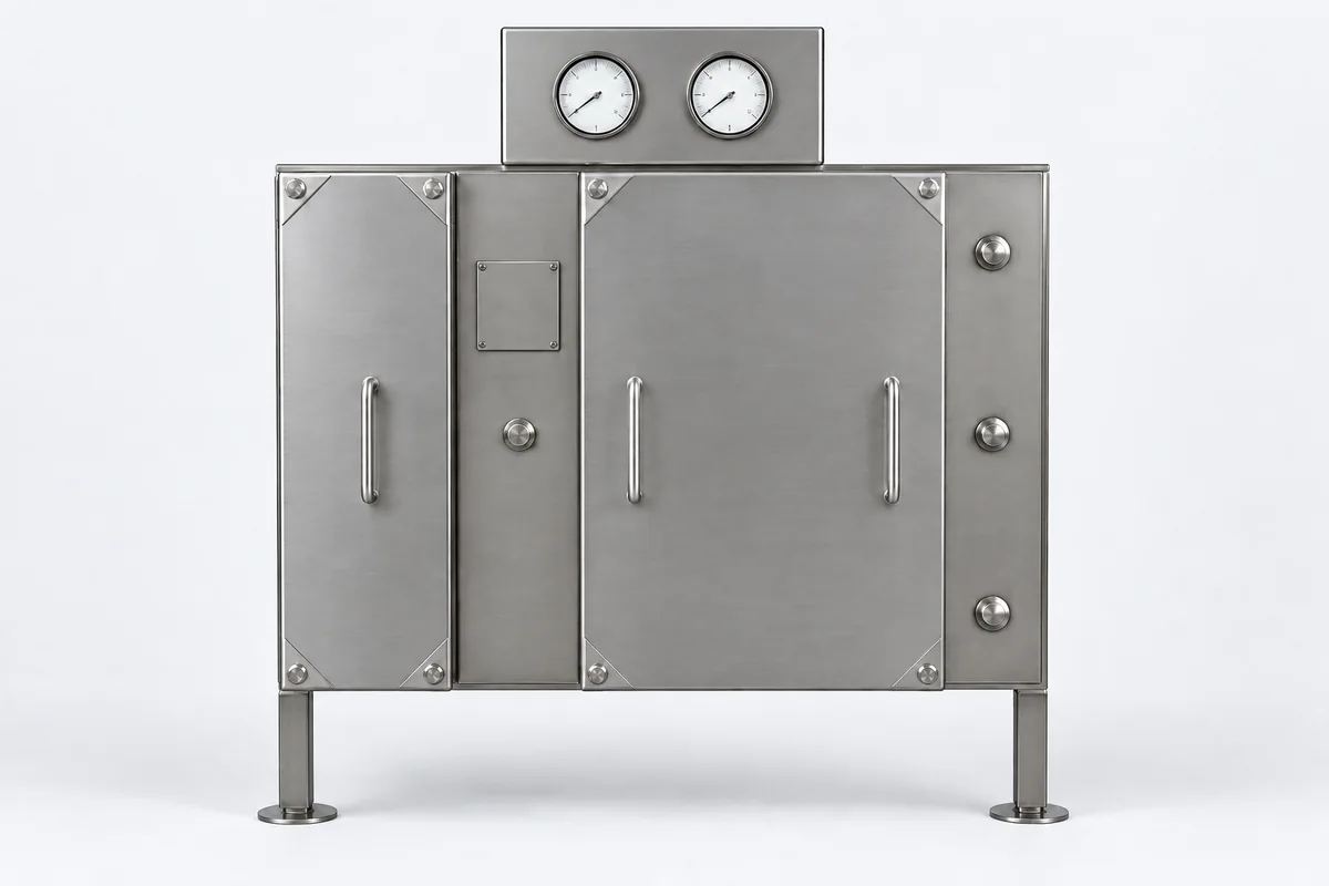
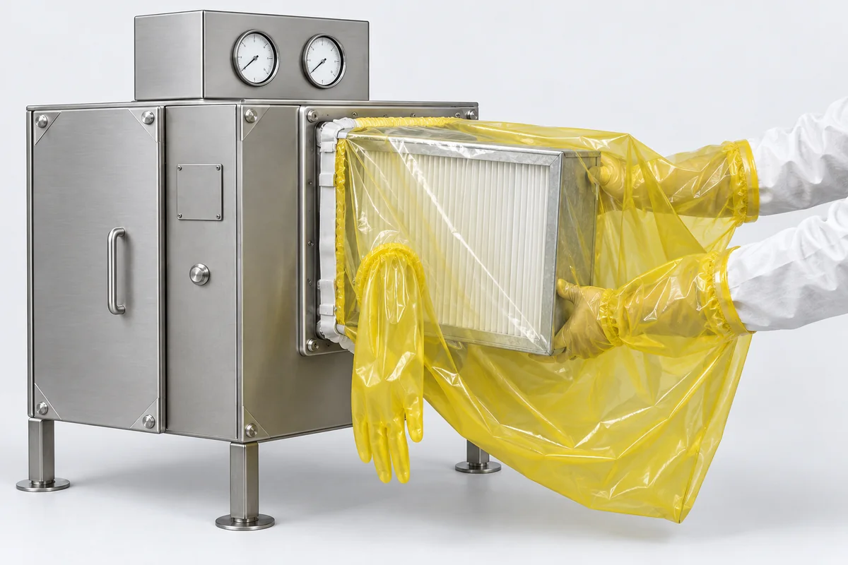
횡형 기종의 측면 인출 도어 설계. 여재를 통째로 빼낼 수 있어 덕트를 뜯을 필요가 없습니다: 도어 판에는 케미컬 여재 단을 가로지르는 차압계와 기류 방향 표시가 있습니다:
 수직형 기종은 설치 면적이 작아 장비 옆이나 벽면에 두기 좋습니다. 왼쪽은 표준 버튼 반면, 오른쪽은 터치 반면에 차압 표시를 더한 것입니다:
 수직형 기종의 현장 실물. 바닥에 캐스터가 있어 옮겨 위치를 잡을 수 있습니다: