What Is an FFU and Why Is It the Heart of a Cleanroom?
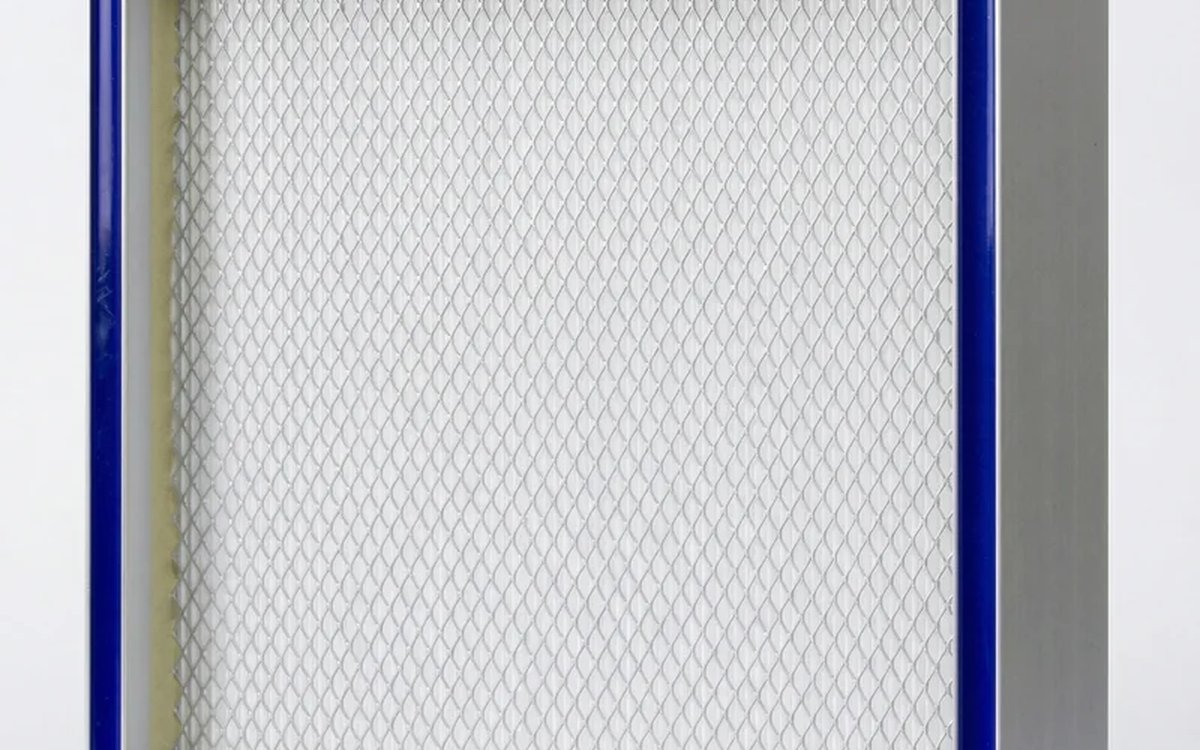
An FFU (Fan Filter Unit) integrates a fan and a high-efficiency filter into a single module that mounts directly into the ceiling T-bar grid of a cleanroom. Each FFU is a self-contained "air supply + filtration" unit — the fan draws return air from above the ceiling plenum, pushes it through a HEPA or ULPA filter, and delivers uniform laminar (or turbulent) airflow downward into the clean zone.
Think of a shower head: the faucet (fan) drives the water flow, and the shower plate (filter) spreads it evenly. An FFU does the same thing — just with air.
Compared to traditional central HVAC ducted supply, the biggest advantage of FFUs is modularity: a cleanroom can have dozens or even hundreds of FFUs. If one fails, you replace that single unit without shutting down the production line.
Three Common FFU Specifications
FFUs on the market come in three main sizes. The table below compares dimensions, airflow, noise, filter compatibility, and other key parameters.
Three Common FFU Specifications Compared
Size, airflow, noise, filter pairing at a glance
| Parameter | Standard 1200×600 | Slim 600×600 | High-cap 1200×1200 |
|---|---|---|---|
| Dimensions (mm) | 1200×600×250 | 600×600×200 | 1200×1200×300 |
| Rated airflow (CMH) | 900–1,200 | 400–600 | 2,000–2,800 |
| Fan power (W) | 120–180 | 60–90 | 250–400 |
| Noise dB(A) | 50–55 | 45–50 | 55–62 |
| Filter pairing | HEPA H13/H14 | HEPA H13/H14 | HEPA H14 / ULPA U15 |
| Face velocity (m/s) | 0.35–0.45 | 0.35–0.45 | 0.35–0.45 |
| Cleanliness class | ISO 5–7 | ISO 5–7 | ISO 3–5 |
Values are typical ranges for common industry specs; brands vary. Airflow based on face velocity 0.35–0.45 m/s.
How to Choose
- ▸Standard 1200×600: The workhorse. Fits ISO 5–7 cleanrooms in semiconductor, flat panel, and pharmaceutical facilities. Over 70% of FFUs installed in Taiwan are this size.
- ▸Slim 600×600: For ceiling-height-constrained installations such as clean benches and lab-scale clean zones. Lower airflow but quieter.
- ▸High-capacity 1200×1200: For ISO 3–4 environments like semiconductor lithography and etch bays that demand very high coverage ratios and ULPA filters.
Speed, Airflow, and Noise: The Three-Way Tradeoff
FFU speed directly determines airflow and noise. Running at 100% delivers maximum airflow and cleanliness — but noise can exceed 55 dB(A), which is uncomfortable for operators over extended shifts.
In practice, most factories run their FFUs at 70–80% speed, balancing "clean enough" with "not too loud."
FFU Speed vs Noise vs Airflow: The Three-Way Tradeoff
Higher airflow → higher noise; production typically runs at 70–80% speed
100 %: Initial qualification, PAO test
80 %: Normal production (most common)
60 %: Night shift / low load / energy-saving
40 %: Standby / unoccupied cleanroom
Data for standard 1200×600 FFU with HEPA H14. EC motor + VFD can reduce noise by 3–5 dB(A).
Practical Recommendations
| Scenario | Suggested Speed | Reason |
|---|---|---|
| PAO integrity test | 100% | Regulatory requirement at full speed |
| Daytime production | 75–85% | Balance cleanliness and operator comfort |
| Night shift / low load | 55–65% | 30%+ energy savings, noise drops to ~44 dB(A) |
| Standby (unoccupied) | 35–45% | Maintain positive pressure only, major energy savings |
AC Motor vs EC/DC Motor: The Energy Equation
FFU fans come with two motor technologies:
AC Motor (Alternating Current)
- ▸Lower cost, simple construction
- ▸Typically three-step switching only (full / half / off), or external transformer
- ▸Efficiency around 50–60%, higher heat output
EC Motor (Electronically Commutated DC)
- ▸20–40% higher unit cost, but built-in variable frequency drive
- ▸Stepless 0–100% speed control, adjustable to 1% increments
- ▸Efficiency 85–92%, saves 40–50% energy
- ▸3–5 dB(A) quieter at the same airflow
- ▸Compatible with group control systems for independent per-unit speed adjustment
For a 1,000-FFU semiconductor fab, switching from AC to EC motors can save approximately USD 60,000–130,000 per year in electricity (varies by tariff and operating hours). Payback is typically 2–3 years.
Filter Pairing: HEPA or ULPA?
The "filtration" half of an FFU is determined by the filter. Choosing the wrong filter means even the best fan cannot achieve the target cleanliness class.
| Filter Grade | Efficiency (0.3 µm) | Pressure Drop (Initial) | Suitable Class | Typical Application |
|---|---|---|---|---|
| HEPA H13 | ≥99.95% | 120–180 Pa | ISO 7–8 | Food, electronics assembly, general cleanrooms |
| HEPA H14 | ≥99.995% | 150–250 Pa | ISO 5–6 | Pharma, semiconductor back-end, flat panel |
| ULPA U15 | ≥99.9995% | 250–350 Pa | ISO 3–4 | Semiconductor front-end, reticle storage |
| ULPA U16 | ≥99.99995% | 300–450 Pa | ISO 1–3 | Extreme cleanliness (advanced nodes) |
Key point: Higher filter grades mean higher pressure drops, which force the FFU motor to work harder. That is why an ISO 7–8 food plant only needs H13 — using ULPA would waste energy and increase noise for no benefit.
Application Scenarios and Spec Pairing
Different industries and cleanliness classes require very different FFU specs and filter combinations. The table below lists five typical scenarios.
FFU Application Scenarios & Spec Pairing
Cleanliness class determines FFU coverage ratio and filter selection
| Scenario | ISO class | FFU spec | Filter | Coverage | Key point |
|---|---|---|---|---|---|
| Semicon litho bay | ISO 3–4 | 1200×600 / 1200×1200 | ULPA U15–U16 | 80–100% | Laminar + ULPA, zero tolerance |
| Semicon back-end packaging | ISO 5–6 | 1200×600 | HEPA H14 | 60–80% | H14 sufficient, cost control |
| Pharma aseptic filling | ISO 5 | 1200×600 | HEPA H14 | 80–100% | cGMP mandates laminar + H14 |
| Food plant packaging | ISO 7–8 | 600×600 | HEPA H13 | 25–40% | Turbulent OK, focus on foreign objects |
| Lab / clean bench | ISO 5 | 600×600 薄型 | HEPA H14 | 局部 100% | Local clean zone, not whole room |
FFU coverage = FFU outlet area / ceiling area. ISO 5+ typically requires 60–100% (laminar). ISO 7–8 only needs 25–40% (turbulent mix).
Selection Workflow: Five Steps
- 1Determine target cleanliness: What ISO class? This drives coverage ratio and filter grade.
- 2Calculate FFU quantity: Coverage = total FFU outlet area ÷ ceiling area. ISO 5 needs 60–100%; ISO 7 only 25–40%.
- 3Choose size: Is the ceiling grid 600 mm or 1200 mm module? Any height constraints?
- 4Choose motor: For >50 FFUs, EC motors + group control pay for themselves in energy savings.
- 5Choose filter: Match HEPA or ULPA to ISO class, and verify the pressure drop is within the motor's capability.
FAQ
Q1: What is the difference between FFU, MAU, and AHU? A MAU (Make-up Air Unit) brings in fresh outdoor air and handles temperature and humidity conditioning. An AHU (Air Handling Unit) is a central air handler that conditions large volumes of return air. An FFU is the terminal device that provides the "last mile" of high-efficiency filtration and air supply. The three typically work together: MAU treats outdoor air → AHU conditions return air → FFU delivers final filtered air into the clean zone.
Q2: How often should FFU filters be replaced? HEPA H14 filters under normal operation last about 3–5 years. The key indicator is pressure drop: replace when terminal pressure drop reaches 2× the initial value (or exceeds 400–450 Pa absolute). Quarterly pressure drop measurements with trend tracking are recommended.
Q3: Are EC motors worth the premium? If you have more than 50 FFUs running 16+ hours per day, the energy savings from EC motors typically pay back in 2–3 years. Group control systems also enable remote monitoring of each FFU's speed and status, reducing maintenance costs.
Q4: Why not use ULPA everywhere? ULPA filters have 50–100% higher pressure drop than HEPA, requiring larger motors, more electricity, and higher noise. For ISO 7–8 environments, HEPA H13 already meets the standard — ULPA would be over-engineering.
Q5: How is FFU coverage ratio calculated? Coverage = total FFU outlet area ÷ cleanroom ceiling area × 100%. For example, a 10 m × 6 m room with 50 units of 1200×600 FFU: outlet area = 50 × 1.2 × 0.6 = 36 m², ceiling area = 60 m², coverage = 60%.